background image

11

Functions

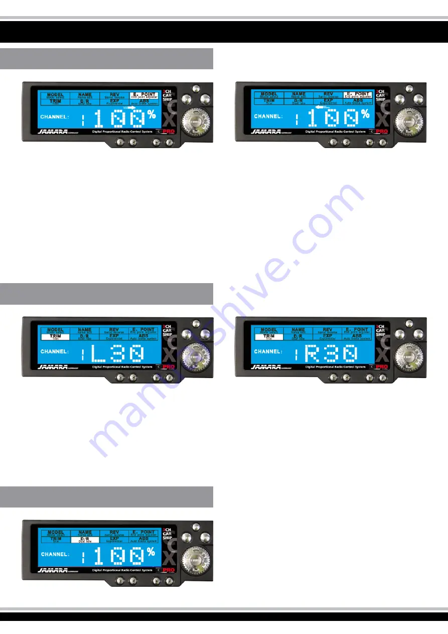
D/R

This setting allows you to limit the adjustment of the servo travel.

Output value is 100%
Displacements from 0 - 100%

Press „Enter“ and choose „D / R“ in the menu. The channel will 
flash. Press „END“ to enter the setting of the channel. Select with 
the  rotary  knob  to  set  the  value  and  press  Enter  to  confirm  the 
value.

TRIM

With this setting you can set the neutral position of the servos.

Output value is N00
Setting of L30 to N00 to R30 and F30 to N00 and B30.
L = left, N = zero, R = Right, F = Forward B = Back

Press „Enter“ and select „TRIM“ in the menu. The channel will flash. Press „END“ to enter the setting of the channel. Select with the rotary 
knob to set the value and press Enter to confirm the value.

E POINT

With this setting you can set the steering angle of your servos. If your steering servo differs at full scale (left or right) differ, you can adjust it 
with this setting.

Output value is 100%.
Displacements from 0 to 120%

Press „Enter“ and select „E POINT“ in the menu. To select the servo direction, press the channel (1, 2 or 3) ind the desired direction (1 = wheel, 
2 = throttle, 3 = third channel key). Press „END“ to enter the setting of the channel. Select with the rotary knob to set the value and press 
Enter to confirm the value.

Summary of Contents for CCX Pro

Page 1: ...Instructions Please read these instructions carefully before use and keep them for future reference CCX Pro 2 4 GHz Ord No 06 1200 GB Free for use in D A E GB F B DK PL FIN GR P I CH...

Page 2: ...system to extreme heat cold or vibration The system should only be operated between 10 and 400C Use a good quality char ger selected from our range and follow the battery manufacturers instructions A...

Page 3: ...gulations referring to the use of radio signals radio control which may be in force within the country where you are operating your model any queries should be addressed to your dealer Please Remember...

Page 4: ...l ABS Temperature Range 15 bis 58 C Operating Voltage 9 6 12 V Low Voltage Warning 9 5 V Receiver Antenna Length 26 cm Voltage 12 V DC 8 Cells Charging Via Charging Socket DSC Port Simulator Socket 3...

Page 5: ...charged before using the system Please be aware that due to the self discharge characteristics of this type of cells that they should always be fully charged prior to use Please refer to the battery...

Page 6: ...Diagram For Electric Models Channel 1 Battery Pack Motor Warning To avoid any short circuit in your receiver please make sure to connect the cables with correct polarity in mind Mount the 2 4 GHz ant...

Page 7: ...g repeat the above procedure until a successful bonding is achieved The diagram illustrate the bonding process and show the locations of the relevant components Programming of the integrated FailSafe...

Page 8: ...oth the transmitter and the receiver illuminate solidly 5 The system is now correctly switch on and operating and can now safely be used 1 Disconnect the receiver battery 2 Switch off the transmitter...

Page 9: ...t the menu The transmitter is turned on the display shows the voltage in volts and the number here 8 and the name in this case ACB of the model By turning the Enter key you can switch between voltage...

Page 10: ...dels in the transmitter Each memory can be set individually for each model The default setting of the transmitter shows no 0 FS0 In the picture you see the space no 8 and the model name ACB Switch the...

Page 11: ...ess Enter and select TRIM in the menu The channel will flash Press END to enter the setting of the channel Select with the rotary knob to set the value and press Enter to confirm the value E POINT Wit...

Page 12: ...the curve of the reaction of the respective channel in relation to the input of the transmitter steering wheel throttle ABS With this setting you can determine if your model is to have the gas or brak...

Page 13: ...relevant direc tion Turning the wheel to the right will make the models wheels turn to right when viewed from above as illustrated Moving the wheel to the left will cause the wheels to turn to the lef...

Page 14: ...mulator Cable in to both items 2 Switch on both your transmitter and your computer 3 Open the simulator software on your computer 4 Follow the software s instructions regarding calibrating your transm...

Page 15: ...15 Notice...

Page 16: ..._ City _______________________________ Phone _______________________________ E mail _______________________________ Please send the catalogue to the following speci alist dealer Your dealer __________...

Reviews: