


PIN ASSIGNMENTS
Product: JH 20T01 M20
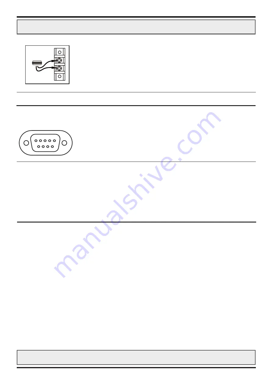
POWER CONNECTOR:
(2x cable eye screws)
Pin Number: Description:
+
+12
VDC
in
-
ground
TOUCHSCREEN D-SUB 9P CONNECTOR FEMALE:
(optional)
Pin Number: Description:
1
DCD
2
RXD
3
TXD
4
DTR
5
GND
6
DSR
7
RTS
8
CTS
9
RI
Product: JH 20T01 M20
10
5 4 3 2 1
9 8 7 6
12-24VDC
85W
POWER
- VDC
+ VDC
POLARITY PROTECTED


