


Xonic
®
100 Series
Jain Technology
Tel. 82-2-856-4114 Fax. 82-2-856-9503
6
Instructions - Transducers Installation
The open channel system may be used in rectangular, circular, trapezoid, or other
shaped channels. Since the transducers create almost no restriction, virtually no head
loss is created. The advanced DSP-based flow computer with cross-correlation and FFT
technology allows this system to work in the most difficult applications, including
those involving liquids with high concentrations of suspended solids & air or a large
noise component. Please read this manual carefully before installation.
e.g. ) Open Channel - Dual Path
Step 1:
Fixing of Mounting
Bracket
Selecting the right mounting place is the most important for ensuring the accuracy.
Please follow below steps to install the mounting bracket.
1)
Install mounting brackets on the A side wall tightly. Considering highest and
lowest water level, select distance between paths or distance between lower path
and the bottom.
2)
Confirm the installation place for the opposite side wall, then install brackets on
the wall tightly.
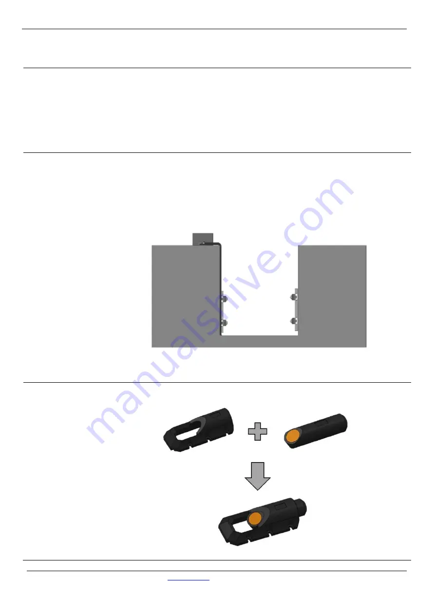
Step 2:
Assembling of
Sensor and Bracket
Insert sensors into brackets tightly.
A side
B side
Summary of Contents for Xonic 100 Series
Page 43: ...Xonic 100 Series Jain Technology www jain co kr Tel 82 2 856 4114 Fax 82 2 856 9503 43...
Page 44: ...Xonic 100 Series Jain Technology www jain co kr Tel 82 2 856 4114 Fax 82 2 856 9503 44...
Page 45: ...Xonic 100 Series Jain Technology www jain co kr Tel 82 2 856 4114 Fax 82 2 856 9503 45...
Page 46: ...Xonic 100 Series Jain Technology www jain co kr Tel 82 2 856 4114 Fax 82 2 856 9503 46...
Page 47: ...Xonic 100 Series Jain Technology www jain co kr Tel 82 2 856 4114 Fax 82 2 856 9503 47...


