Pro I: Analog Input Modules
Pro-AIn-8/16 Rev. A
ADwin
56
ADwin-Pro
Hardware, manual version 2.9, June 2006
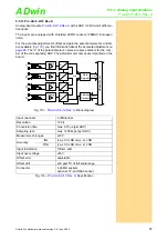
Fig. 91 – Pro-AIn-8/16-D Rev. A: Pin assignment
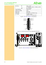
Setting the Input Voltage Range
The input module
is equipped with an ADC whose input
voltage range is adjustable by 3jumpers. As a default setting, the ADC is set
to the voltage range of ±10V. The settings for other voltage ranges can be
found in
: Board and front panel
After every jumper setting you have to recalibrate the ADC, in order to assure
correct measurement results. The individual steps are described in the
.
For the accurate adjustment of offset and gain the potentiometers UO (unipo-
lar) or BO (bipolar) as well as GAIN are available (
).
ANALOG IN 1 (-)
ANALOG IN 2 (-)
ANALOG IN 3 (-)
ANALOG IN 4 (-)
ANALOG IN 5 (-)
ANALOG IN 6 (-)
ANALOG IN 7 (-)
ANALOG IN 8 (-)
AGND
RESERVED
ANALOG IN 1 (+)
ANALOG IN 2 (+)
ANALOG IN 3 (+)
ANALOG IN 4 (+)
ANALOG IN 5 (+)
ANALOG IN 6 (+)
ANALOG IN 7 (+)
ANALOG IN 8 (+)
AGND
RESERVED
DGND
19
18
17
16
15
14
13
12
11
10
9
8
7
6
5
4
3
2
1
37
36
35
34
33
32
31
30
29
28
27
26
25
24
23
22
21
20
RESERVED
RESERVED
19AD7809
FPGA
FPGA
ON
1 2 3 4 5 6 7 8
A0 A1 A2 A3 A4 A5 A6 A7
DC-DC-converter
2631
2631
2631
2631
2631
2631
A
D
S
7809
F3
2
LS
19
IN
A
103
MP
C
507
DC/DC-converter
103
UO
BO
Gain
UNI
BIP
10V
20V
10V
20V
AIN8/16
ANALOG
INPUT
1
2
3
4
5
6
7
8
AIN8/16
ANALOG
INPUT
Jumpers
Potentiometers
1
2
3
Voltage range
J1
J2
J3
±5V bipolar
10V 20V BIP
±10V bipolar
(default)
10V 20V BIP
0...10V unipolar 10V 10V UNI
not allowed
(0…20V)
20V 20V UNI
Fig. 93 –
:
Jumper settings for the input voltage
range
Potenti-
ometer
Adjustment of
Gain
Gain factor
BPO
Offset (bipolar set-
ting)
UPO
Offset (unipolar set-
ting)
:
Function of the potentiometers

