Pro I: Digital-I/O- and Counter Modules
Pro-CNT-PW4 Rev. A
ADwin
122
ADwin-Pro
Hardware, manual version 2.9, June 2006
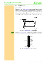
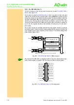
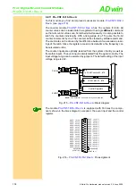
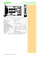
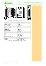
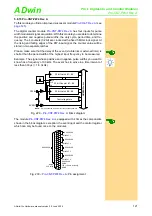
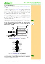
Fig. 232 –
: Board and front panel
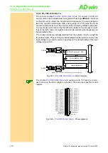
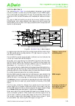
falling edge
rising edge
Input PW1
Latch 1
Latch 5
Input PW2
Latch 2
Latch 6
Input PW3
Latch 3
Latch 7
Input PW4
Latch 4
Latch 8
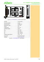
Fig. 231 –
: Allocation of the latches
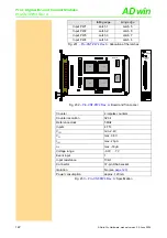
Counter
4 impulse counters
Counter resolution
32 bit
Reference clock
5MHz
Inputs
4 TTL
V
IH
min. 2.4V
V
IL
max. 0.8V
I
IH
max. 20µA
I
IL
max. -50µA
Voltage range
-0.3V … 7V
Event input
1
Input resistance
10k
Ω
Connector
37-pin DSub socket
Isolation
No (see
Power consumption
approx. 120mA
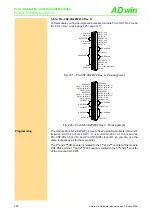
Fig. 233 –
: Specification
19CNT01
ON
1 2 3 4 5 6 7 8
A0 A1 A2 A3 A4 A5 A6 A7
FPGA
FPGA
A
B
T
16245
LS19
LS19
LS19
LS19
LS19
LS19
LS19
OCX
FPGA
FPGA
FP
G
A
CNT-PW4
COUNTER
INPUT

