Pro I: Digital-I/O- and Counter Modules
Pro-DIO-32 Rev. B
ADwin
96
ADwin-Pro
Hardware, manual version 2.9, June 2006
5.8.2 Pro-DIO-32 Rev. B
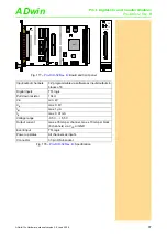
The digital input/output module
provides 32 programmable
digital input and output channels at TTL levels. The channels can be config-
ured as blocks of 8 bits as inputs or outputs by
ADbasic
instructions (not indi-
vidually as previous model). The channels are configured as inputs after power
up.
With the new command
DIGOUT_F
the setting or resetting of single outputs is
realized quicker and needs much less program memory (the previous com-
mand
DIGOUT
can still be used).
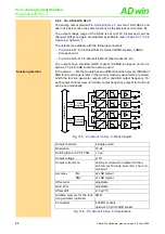
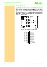
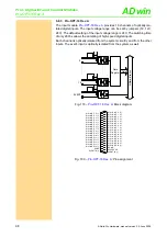
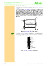
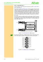
Fig. 175 –
: Block diagram
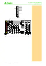
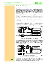
Fig. 176 –
: Pin assignment
ADwi
n
-P
ro
bus
0
1
31
. . . . . . . . . . .
. .
. . . . . . . . . . . . . . . . . . . . . . . .
2
3
30
EVENT
Data
Register
Data
10k
10k
10k
10k
10k
10k
10k
Bus-
Trans-
ceiver
D00:07
Bus-
Trans-
ceiver
D08:15
Bus-
Trans-
ceiver
D16:23
Bus-
Trans-
ceiver
D24:31
DIG I/O, BIT 1
DIG I/O, BIT 3
DIG I/O, BIT 5
DIG I/O, BIT 7
DIG I/O, BIT 9
DIG I/O, BIT 11
DIG I/O, BIT 13
DIG I/O, BIT 15
DIG I/O, BIT 17
DIG I/O, BIT 19
DIG I/O, BIT 21
DIG I/O, BIT 23
DIG I/O, BIT 25
DIG I/O, BIT 27
DIG I/O, BIT 29
DIG I/O, BIT 31
DGND
EVENT IN
DIG I/O, BIT 0
DIG I/O, BIT 2
DIG I/O, BIT 4
DIG I/O, BIT 6
DIG I/O, BIT 8
DIG I/O, BIT 10
DIG I/O, BIT 12
DIG I/O, BIT 14
DIG I/O, BIT 16
DIG I/O, BIT 18
DIG I/O, BIT 20
DIG I/O, BIT 22
DIG I/O, BIT 24
DIG I/O, BIT 26
DIG I/O, BIT 28
DIG I/O, BIT 30
DGND
+5V, <100mA (fused)
DGND
19
18
17
16
15
14
13
12
11
10
9
8
7
6
5
4
3
2
1
37
36
35
34
33
32
31
30
29
28
27
26
25
24
23
22
21
20


