


ADwin
LS Bus, Manual version 1.0, September 2006
5
HSM-24V
ADwin
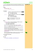
Fig. 3 – Pin assignment LS bus
3.2 Software
Include File
The functions of the module
are easily programmed with
ADbasic
instructions. The instructions are contained in an include file; include this file at
the top of the program with this line
#INCLUDE ADWL16.inc
The sintructions of the following table are described on the following pages or
in the online help:
Input LS bus (male)
Output LS bus (female)
1
2
3
4
5
6
7
8
9
SIGNAL HIGH
RESERVED
SIGNAL GND
SIGNAL LOW
RESERVED
RESERVED
RESERVED
5
4
3
2
1
9
8
7
6
SIGNAL GND
RESERVED
SIGNAL HIGH
RESERVED
SIGNAL LOW
RESERVED
RESERVED
Instruction
Function
LS_DIO_INIT
Initialize modul HSM-24V.
LS_DIGPROG
Set channels as inputs or outputs.
LS_WATCHDOG_INIT
Disable watchdog counter or enable and set
watchdog time.
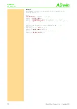
LS_DIG_IO
Set level of digital outputs and return current
levels. This instruction is valid for 1 module only.
Fig. 4 – Instructions for
, overview


