background image

18

J-445/J-435 Export

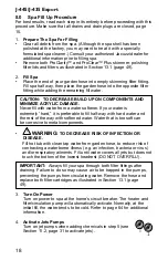
8.0  Spa Fill Up Procedure

For best results, read each step in its entirety before proceeding with this 

procedure. Make sure that all drains and drain plugs are closed, page 

15.
1. 

Prepare The Spa For Filling

•  Clear all debris from the spa. (Although the spa shell has been 

polished at the factory, you may want to treat it with a specially 

formulated spa cleaner.) Consult your authorized Jacuzzi dealer for 

additional information prior to filling spa.

•  Remove both ProClarity™ and ProClear™ Plus skimmer, polishing 

filter lids and filters as illustrated in Section 13.1 (page 49).

2. 

Fill Spa

•  Place the end of your garden hose into empty skimming filter fitting. 

Fill spa half way, then place the garden hose into the opposite filter 

fitting while adding the remaining fill water.

CAUTION:


TO DECREASE BUILD UP ON COMPONENTS AND 

MINIMIZE ACRYLIC DAMAGE.

Never fill with water from a water softener. If your water is 

extremely “hard,” it is preferable to fill half-way with hard water and 

the rest of the way with softened water. Water that is too soft can 

be corrosive to metal components.

• 

!


WARNING: 

TO DECREASE RISK OF INFECTION OR 

DISEASE.


Fill hot tub with clean tap water from garden hose, to reduce risk of 

contracting a waterborne illness (e.g. an infection, bacteria or virus) 

and/or respiratory ailments. Fill until water covers all jets but does not 

touch the bottom of the lowest headrest (DO NOT OVERFILL!).

IMPORTANT:

  Always fill your spa through both filter fittings after 

draining. Failure to do so may cause air to be trapped in the pumps, 

preventing the pumps from circulating water. Remove the hose and 

replace both filter cartridges as illustrated in Section 13.1 (page 

49).

3. 

Turn On Power


Turn on power to spa at the home’s circuit breaker. The heater and 

filter/circulation pump will automatically activate. Normally, at the 

initial fill, the water tends to be cold. Refer to page 64 for additional 

information.

4. 

Activate Jets Pumps


Turn on jet pumps when adding chemicals in step 5 (see 

Section 11.2, page 31 to activate jets).

1

Summary of Contents for J-435

Page 1: ...J 435 J 445 EXPORT OWNER S MANUAL 6530 274EE Rev C...

Page 2: ...res an annual bulb replacement to properly sanitize your water TO DECREASE RISK OF INFECTION OR DISEASE Always maintain your spa filter as outlined below to ensure healthy spa water Refer to pages 49...

Page 3: ...Requirements 17 8 0 Spa Fill Up Procedure 18 9 0 Spa Features 22 9 1 J 445 Spa Features 22 9 2 J 445 Massage Waterfall Selector Diagram 23 9 3 J 445 Air Controls Diagram 24 9 4 J 435 Spa Features 25 9...

Page 4: ...ng the Spa 45 12 10 Programming the Time and Date 46 12 11 Programming the Language 47 12 12 Units Display 48 12 13 System Information 48 13 0 Spa Maintenance 49 13 1 Cleaning the Filter Cartridges 49...

Page 5: ...rcuit Board Wiring Diagrams 69 17 1 Export 50Hz Wiring Diagram 69 17 2 Dip Switch Settings 70 17 3 Single Service 50Hz Connection 71 17 4 Dual Service 50Hz Connection 72 17 5 Three Service 50Hz Connec...

Page 6: ......

Page 7: ...undesired operation This equipment has been tested and found to comply with the limits for a Class B Digital Device pursuant to Part 15 of the FCC Rules These limits are designed to provide reasonabl...

Page 8: ...lead to drowning or severe injury Never use the spa unless all suction guards filter filter lid or skimmer assembly are installed to prevent body and or hair entrapment Never operate or use the spa i...

Page 9: ...er GFCI as required by NEC Article 680 42 4 WARNING RISK OF SEVERE INJURY OR DEATH Extreme caution must be exercised to prevent diving or jumping into the spa or slipping and falling which could resul...

Page 10: ...ng spa use may lead to unconsciousness with the possibility of drowning 7 WARNING RISK OF SEVERE INJURY OR DEATH Prolonged immersion in a spa may be injurious to your health Observe a reasonable time...

Page 11: ...een given supervision or instruction concerning use of the appliance by a person responsible for their safety 12 NOTE This spa is not intended nor designed to be used in a com mercial or public applic...

Page 12: ...n or skimmer assembly This has been reported in persons who when submerge themselves underwater allowing hair to come close and or within the reach of the suction fittings suction covers or skimmer as...

Page 13: ...or skimmer assembly Never allow children to play or get near the suction fittings suction covers filter filter lid or skimmer assembly 3 2 Hyperthermia Prolonged immersion in hot water may induce hyp...

Page 14: ...ls ladders drains or other similar hardware within 10 feet 3m of the spa shall be bonded to the equipment grounding buss with copper conductors not smaller than No 6 AWG 10 mm 5 SAVE THESE INSTRUCTION...

Page 15: ...ggest that you take into consideration The proximity to changing area and shelter especially in colder weather The pathway to and from your spa this should be free of debris so that dirt and leaves ar...

Page 16: ...e spa rests on has adequate drainage and can handle the entire contents of the spa Be sure to make provisions for ceilings and other structures that may be below the spas installation Areas around you...

Page 17: ...is slow or produces an error the proposed installation site is not a good choice It may be necessary to choose another spa installation site Relocate your home Wi Fi router closer to the spa Install a...

Page 18: ...ivity of the Wi Fi module check the maximum number of devices that can be connected to the Access Point that the customer is using 5 0 General Electrical Safety Instructions Your new Jacuzzi spa is eq...

Page 19: ...d switch or circuit breaker to open all ungrounded supply conductors to comply with Section 422 20 of the National Electrical Code USA ANSI NFPA 70 The disconnecting means must be readily accessible t...

Page 20: ...WIRES MUST BE SECURELY CONNECTED or equipment damage could result 10 Install control access box door and reinstall the foam boards and cabinet panel s Power on Lamp on DANGER TURN POWER OFF DO NOT LOO...

Page 21: ...ply Optional 13 ProLink Remote Monitoring System Module Optional 14 CLEARRAY Pro3tect Ozone Optional 15 Drain F1 10A 250VAC F7 30A 30A F6 K12 K1 K9 K15 K14 T1 TB1 4 3 2 1 K5 J22 N A N A J43 J2 K13 J65...

Page 22: ...Blu N1 BREAKER TERMINAL CONNECTIONS L1 All Components Blu Brn N1 L1 TB1 TB3 Green Factory Default Blu Blu Brn Brn Green L1 L2 N1 N2 TB1 TB3 Blu Brn Brn Brn Green L1 L2 N1 L3 TB1 TB3 Service 1 Service...

Page 23: ...s configuration the heater will operate while one or two jets pumps are running The service 1 breaker will include connection for all components Export 50 Hz Two and Three Breaker Connections Dual Ser...

Page 24: ...er is extremely hard it is preferable to fill half way with hard water and the rest of the way with softened water Water that is too soft can be corrosive to metal components WARNING TO DECREASE RISK...

Page 25: ...to a comfortable temperature follow these steps The display on the control panel displays the actual temperature of the spa water Tap or to increase or decrease the water temperature in 0 5 C 1 F inc...

Page 26: ...l Average Sodium Model Fill Volume Dichlor J 445 370 Gal 1 401 L 9 3 oz J 435 360 Gal 1 363 L 9 0 oz Use average fill volume for chemical maintenance 10 Leave spa cover open during this step to allow...

Page 27: ...while the cover is open and accessible to small children and animals To decrease the possibility of contracting a waterborne ill ness e g an infection bacteria or virus and or respiratory ailments mai...

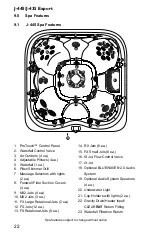
Page 28: ...ll 7 Massage Selectors with lights 2 ea 8 Footwell Filter Suction Covers 4 ea 9 NX2 Jets 4 ea 10 MX2 Jets 3 ea 11 FX Large Rotational Jets 2 ea 12 FX Jets 12 ea 13 FX Rotational Jets 8 ea 14 RX Jets 8...

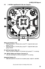
Page 29: ...groups 1a 1b Massage selector 2 diverts jets pump N 1 output between jets groups 2a 2b IX Jet Flow Control Valve 3 Valve 3 controls output to IX Jet when jets pump N 1 is running Jets Without Massage...

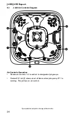
Page 30: ...1 1 1 1 5 2 2 2 4 3 3 4 1 1 1 3 Air Controls Operation Rotate air controls 1 4 to add air to designated jet groups Footwell IX Jet 5 draws air at all times when jets pump N 1 is running This jet has...

Page 31: ...h lights 2 ea 8 Footwell Filter Suction Covers 4 ea 9 NX2 Jets 6 ea 10 MX2 Jets 3 ea 11 FX Large Rotational Jets 3 ea 12 FX Jets 9 ea 13 FX Rotational Jets 6 ea 14 RX Jets 8 ea 15 FX Small Jets 10 ea...

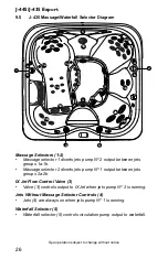
Page 32: ...n jets groups 1a 1b Massage selector 2 diverts jets pump N 1 output between jets groups 2a 2b IX Jet Flow Control Valve 3 Valve 3 controls output to IX Jet when jets pump N 2 is running Jets Without M...

Page 33: ...1 1 1 4 2 2 2 3 3 1 1 1 1 1 3 3 3 Air Controls Operation Rotate air controls 1 3 to add air to designated jet groups Footwell IX Jet 4 draws air at all times when jets pump N 1 is running This jet has...

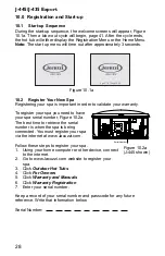
Page 34: ...have your spa serial number Figure 10 2a The best time to retrieve the serial number is when the spa is being connected You must register your spa via the internet at www Jacuzzi com Follow these ste...

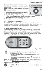
Page 35: ...ur new Jacuzzi spa A Home Menu Control Buttons The Home Menu Figure 10 3a provides access to spa functions and programming Operation is made easy by the interactive control panel If there is no activi...

Page 36: ...ed The icon will also appear under the Temperature reading as a reminder page 62 Tap to view the condition that requires attention Invert Button Tap to invert the display image Heater ON icon Will dis...

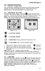
Page 37: ...image 1 Tap the Jets 1 button to turn the pump on and off 2 Tap the Jets 2 button to turn the pump on and off 3 When a jets pump is on the button will have a blue inner glow Note Auto Turn Off Anytime...

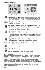
Page 38: ...se Tap to decrease the blending speed of the colors to the minimum speed of 0 Speed Selector Icon Tap or to select the blending speed for the light colors Color Selector Tap a color to select a single...

Page 39: ...t setting Auxiliary Settings Tap to use your Auxiliary device with the stereo Volume Up Tap to increase the volume The range is from 0 to 30 in increments of 1 Volume Down Tap to decrease the volume T...

Page 40: ...creen 4 Once the connection is established the Bluetooth BT icon on the screen will be highlighted confirming the connection 5 If asked for a password enter the password 0000 and then connect 6 If the...

Page 41: ...us menu Invert Button Tap to invert the display image 11 7 CLEARRAY on Demand The CLEARRAY on demand feature activates the water purification system for a period of 1 hour Tap to turn the system on Du...

Page 42: ...water between various jet systems Simply turn massage selector to position A Combo B or C to divert water pressure to various jet groups Note The massage selector valve s is designed to operate in pos...

Page 43: ...the heating and filtration programming page 38 Water Care Water Care Provides access to the water care programming page 42 WiFi Wi Fi Provides access to the optional Wi Fi programming page 44 50Hz mo...

Page 44: ...nu Then select one of the heating settings A Auto heating 1 When programmed to Auto the spa will maintain the water temperature to the set temperature Heating will occur when necessary 2 To select thi...

Page 45: ...culation pump CLEARRAY and ozone unit if applicable are activated The factory default cycle starts at 12 00 AM and last for 8 hours If you elect to keep this setting then you can skip this section In...

Page 46: ...ather the water temperature in the spa may exceed the set temperature This condition may occur due to heat transference from the filter circulation pump and jets pumps If the water temperature is high...

Page 47: ...M every day Each cycle will last 10 minutes for a total of 20 minutes every day To activate this mode tap next to Frequent Time and duration cannot be altered 4 Tap to return to the Heat Filter Menu T...

Page 48: ...f the power is interrupted 1 From the Water Care Menu you can to set the CLEARRAY UV bulb timer Figure 12 7c 2 Tap or to change the days in 10 day increments The range is from OFF to 365 days The CLEA...

Page 49: ...will reappear in 10 days Refer to Section 13 1 page 49 for filter location C Programming the ProClarity ProClear Filter Timer A programmable filter timer can be set to remind you when to clean or rep...

Page 50: ...display page 65 Follow the previous instructions to reset the timer The filter must be replaced Refer to Section 13 1 page 49 for filter location If you tap snooze the message will clear but the erro...

Page 51: ...enter the Lock Menu if one of the three settings is locked it will be highlighted Orange A Temp Lock Figure 12 9b 1 Tap to lock the temperature feature 2 Tap the first block to select a number Use or...

Page 52: ...eezing conditions exist D To Unlock Figure 12 9c 1 Enter the Lock menu The type of lock that is active will already be highlighted in Orange 2 Tap the first block to start entering the code Then move...

Page 53: ...nth block 1 30 2015 to program 3 Tap or to make changes 4 Tap the day block 1 30 2015 to program 5 Tap or to make changes 6 Tap the year block 1 30 2015 to program 7 Tap or to make changes 8 Tap to sa...

Page 54: ...ts SETTINGS F C Units 12 13 System Information This menu will display the current information for the spa From the Settings Menu tap or to highlight the System Information Menu tab in Orange Tap Syste...

Page 55: ...ever replace a suction fitting or suction cover with one rated less than the flow rate marked on the original suction fitting Using improper suction fittings or suction covers can create a body or hai...

Page 56: ...ing filter cleaning procedure The circulation pump filter goes on the side that has the wall fitting with the grids Figure 13 1b Note Do not attempt to wash the ProClarity depth filter B and the ProCl...

Page 57: ...ster H 1 2 3 Once the filter pins are removed rotate the filter cartridge handle counterclockwise to unthread from the filter canister You can clean the filter 1 and canister 3 but you must replace th...

Page 58: ...onto the filter cover clips as shown you can flip the filter skimmer and use the back side to extend usage N Spa Shell Reinstall the skimmer shield over the filters Then turn power to spa back on 13...

Page 59: ...on to release the panel door from the spa frame Figure 13 2b 3 Slowly and gently tilt the panel forward and then lift up to remove This will expose the equipment bay for easy access to the components...

Page 60: ...prevent it from turning then loosen and remove the front cap to expose the underlying male hose threads Figure 13 2j 3 Attach a garden hose to the exposed threads Figure 13 2k 4 Gently rotate the larg...

Page 61: ...able Regular monthly cleaning and conditioning vinyl is strongly recommended and may increase the longevity of your cover Jacuzzi chemicals are for use in the U S only A To clean and condition the enc...

Page 62: ...Primary Filter Cycle page 39 and that auto heating is selected Section 12 1 Auto Heating page 38 to protect against damage to the spa If you do not intend to use your spa or if there is a prolonged p...

Page 63: ...e length of time consider replacing the UV bulb when you resume use of your hot tub 11 Re install cabinet panels foam boards and cover spa so that no casual moisture can enter into it Consult your Jac...

Page 64: ...rior surface scaling In addition the ability of the sanitation agents to keep the spa clean is severely affected as the pH moves beyond the ideal range That is why almost all spa water test kits conta...

Page 65: ...acteria viruses and algae in portable spas The ultraviolet light otherwise known as UV C or germicidal light inactivates the microorganisms disrupting the DNA so that it cannot reproduce and is consid...

Page 66: ...connection may vary by model 1 Turn the breaker to the spa OFF DRAIN YOUR SPA Note If you are only replacing the UV bulb then the spa does not have to be drained You will need to drain it if you are...

Page 67: ...leaners as they can scratch the quartz tube surface 8 Rinse the quartz tube with clean water to completely remove any cleaning products that were used in step 7 9 Replacing quartz tube Remove the blac...

Page 68: ...V bulb which contains mercury Dispose of the bulb in accordance with disposal laws See www lamprecycle org 19 Once power is activated you can check the ballast Figure 14 5g to see if the CLEARRAY Syst...

Page 69: ...limit temperature sensor is not functional Heater is disabled This must be repaired only by a qualified authorized service organization or service technician 6 Shorted Water Temp Sensor The temperatu...

Page 70: ...spa will flash on and off as an indication that the spa is an overheat condition The heater icon will be blinking and the error icon will be displayed under the temperature 13 Overheat protection DO...

Page 71: ...s having trouble communicating to your spa Contact your authorized dealer or service organization 20 Wi Fi Com Error The Wi Fi module is having trouble communicating to your spa Contact your authorize...

Page 72: ...ou need press and hold your finger over the temperature reading for about 5 seconds The temperature reading will start to blink to indicate the system is ready Tap to raise the temperature up to 41 C...

Page 73: ...er PUMP DOES NOT OPERATE Activate the JETS 1 If no sound is detected or if a buzzing sound is detected turn off power to the spa and contact your dealer or service center 2 If motor operates but no wa...

Page 74: ...of time contact your dealer or authorized service center FILTER CIRCULATION PUMP OFF 1 Verify filter circulation pump is programmed to run page 39 2 Make sure there are no errors preventing the pump...

Page 75: ...J34 J29 J50 J56 J57 J37 K8 K4 K6 1 4AT 250VAC WATER WATER TEMP TEMP SERIAL ADCM FLOW HI LIMIT TEMP J16 J17 J18 J1 J9 J11 J13 J14 J15 J10 J24 ZONE 2 J23 ZONE 1 J26 ZONE 4 TOPSIDE C58 C57 K2 GFCI TRIP J...

Page 76: ...LOCATION 1x40A or 1x16A 1x32A 1x16A 1x20A 3x16A 1 2 3 4 5 6 7 8 9 10 ON OFF ON OFF ON OFF OFF OFF OFF OFF ON OFF 1 2 3 4 5 6 7 8 9 10 ON OFF OFF ON OFF OFF OFF OFF OFF OFF ON OFF 1 2 3 4 5 6 7 8 9 10...

Page 77: ...del spas Both pumps and the heater will be allowed to operate at the same time Three Phase Service 3x16A This setting is for all two pump model spas Both pumps and the heater will be allowed to operat...

Page 78: ...Service Jumper Wiring Wire From To 1 J33 J51 2 J37 J53 3 J59 J38 TB1 D C B A J51 J49 J59 J44 J37 J38 J53 J45 J46 J66 J47 J41 J58 J42 J31 J32 J33 J40 J64 J36 J35 1 2 3 4 GRN N2 BLU L1 BRN N1 BLU L2 BR...

Page 79: ......

Page 80: ......
Reviews: