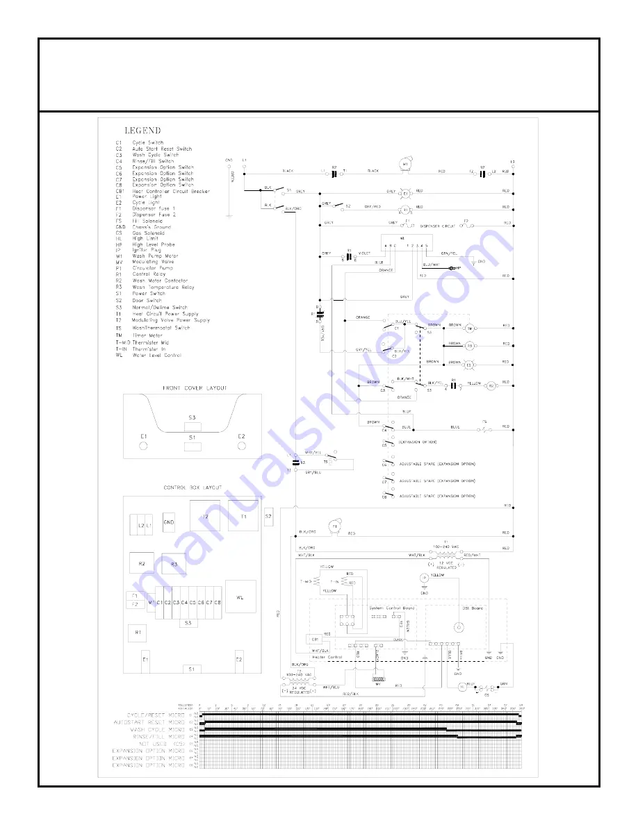
Tempstar TGP
ELECTRICAL DIAGRAM
208/240 VOLT - 50 HERTZ - 1 PHASE
39
Page 1: ...FOR DOMESTIC UNITS FOR JACKSON MODEL TEMPSTAR TGP Jackson MSC Inc P O BOX 1060 HWY 25E BARBOURVILLE KY 40906 FAX 606 523 9196 PHONE 606 523 9795 www jacksonmsc com An Company DUAL TEMPERATURE GAS HEAT...
Page 2: ...NG THERMISTORS 10 CONTROL BOARD LED LIGHT INDICATIONS 11 TROUBLESHOOTING 12 DIMENSIONS 19 TABLE DIMENSIONS 20 PHOTOGRAPHS Main Assembly 21 Control Box Assembly Front View 22 Control Box Assembly Top V...
Page 3: ...7 WATER REQUIREMENTS INLET TEMPERATURE 70 140 F INLET TEMPERATURE 21 11 60 C GALLONS PER HOUR 52 0 LITERS PER HOUR 196 84 WATER LINE SIZE I P S Minimum 3 4 WATER LINE SIZE I P S Minimum 1 9 CM DRAIN...
Page 4: ...ine line strainer using copper pipe It is recom mended that a water shut off valve be installed in the water line between the main supply and the machine to allow access for ser vice The water supply...
Page 5: ...the gas train When making the connection to the booster unit take care to start the gas line fitting by hand and tighten by hand to avoid cross thread ing Tighten fitting with a wrench taking care no...
Page 6: ...uman beings In order to do this ware must be properly prepared prior to being placed in the machine DAILY MACHINE PREPARATION Refer to the section entitled PREPARATION at the top of this page and foll...
Page 7: ...in control box supplies 12vdc to the electronics control drawer location in the lower section of the unit The electronics control board ECB is the brain of the system The ECB receives various inputs a...
Page 8: ...ure above the required temperature The stabilization temperature may be adjusted by means of a potentiometer located on the ECB This is referred to as the T set normally 4 25vdc The recirculating pump...
Page 9: ...lockwise CW until flashing Green LED on control board turns off The recirculating pump will also turn off 6 To ensure that the trim screw has not been turned too far CW turn CCW very slowly until Gree...
Page 10: ...tion 6 With your multi meter set on DC volts attach to the molex plug going to the modulating valve NOTE Do not disconnect molex plug Insert probes in the rear of one side so the contact is made with...
Page 11: ...perature To test the setting or to reset the temperature of the rinse water make sure the unit is on and the green LED on the board is flashing steadily Insert the NEGATIVE Black Common probe of a mu...
Page 12: ...emperature at the T in Thermistor There is a BLACK test point along the top edge of the control board on the right side of center This is where the NEGATIVE Common Black probe of a multi meter is inse...
Page 13: ...power to the ECB C ECB may have never recieved an AUTO CALIBRATION D ECB may be damaged due to high voltage E Control chip in ECB may be misaligned not fully inserted or damaged 2 Green LED is a illum...
Page 14: ...cted correctly If so replace door switch Misadjusted or faulty cycle reset cam microswitch Replace microswitch No water supply to machine Check to ensure that all water valves are open and that water...
Page 15: ...id level control board or probe Check voltage going to each component and ensure they are wired correctly If satisfactory replace the defective part Door switch shorted out wired incorrectly Check the...
Page 16: ...are tight Compression fitting over compressed Replace compression fitting NPT fitting cross threaded Replace the fitting Loose fitting Using an approved leak detector determine which fitting is loose...
Page 17: ...heck for kinks in flexible gas supply line Improper circulation through system Check recirculating pump operation Check for obstructions T set needs adjustment Ensure set point is approximately 4 25 V...
Page 18: ...HE CIRCUIT BOARDS Circuit chip microprocessor pins not fully inserted into its sockets Check for bent pins Ensure chip fully inserted by gently pressing with thumb T mid thermistor reading incorrectly...
Page 19: ...lve and the modulating valve This tapping helps to free the piston Ignition wire loose or broken Check wire for continuity Check connection to both the DSI and spark probe Improper gap on spark probe...
Page 20: ...type of gas being used Remove burner manifold and check correct nozzle orifice size Gas leak may be present Check for localized large yellow flame or a flame located above the burner Obstruction in he...
Page 21: ...ONS LEGEND LETTER A B C D E F G H I J DIM IN 2 1 2 2 1 2 25 1 4 28 32 8 75 60 3 4 17 34 DIM CM 6 35 6 35 64 14 71 12 81 28 20 32 190 5 154 31 43 18 86 36 LETTER K L M N O P Q R S T DIM IN 6 9 11 1 2 1...
Page 22: ...ONS CONNECTION TO DISHMACHINE TABLE DIMENSIONS STRAIGHT THROUGH INSTALLATION C OPENING D E A B A C OPENING D C G F ROLL A B D C OPENING 25 1 4 64 14 CM LETTER DIM IN DIM CM A 4 MIN 10 16 MIN B 2 1 2 6...
Page 23: ...75 06 1 Front Panel 5700 002 19 44 07 1 Left Side Panel 5700 031 89 63 08 1 Incoming Plumbing Assembly 208v 5700 002 21 09 09 1 Right Door Assembly 5700 002 21 33 10 1 Cantilever Arm Assembly 5700 00...
Page 24: ...2 X 3 8 Phillips Truss Head 5305 173 12 00 05 1 Delime Manual Wash Switch 5930 301 21 18 06 1 On Off Power Switch 5930 011 49 55 07 1 Delime Normal Decal 9905 011 34 96 08 1 Timer 220v 50 8 cam 5945 0...
Page 25: ...Temperature 5945 109 03 69 07 1 Timer 220v 50hz 8 Cam 5945 001 99 08 08 1 Fuse Holder 5920 401 03 14 09 1 Relay Control 240v 50 60hz Top Mount 5945 111 47 51 10 1 Liquid Level Control 220v 6680 200 08...
Page 26: ...or Guide Right Front 5700 021 33 19 03 28 Screw 1 4 20 x 1 2 5305 274 02 00 03 28 Washer s s 1 4 ID 5311 174 01 00 03 28 Locknut 1 4 20 s s Hex w Nylon Insert 5310 374 01 00 04 1 Door Guide Left Rear...
Page 27: ...1 33 04 2 Plug Cantilever 5340 011 35 00 05 2 Cantilever Arm Connector 5700 011 90 99 06 1 Cantilever Arm 5700 031 50 67 07 4 Washer s s 1 4 ID 5311 174 01 00 07 4 Locknut 1 4 20 s s Hex w Nylon Inser...
Page 28: ...77 05 1 Thermostat Wash Temperature Over Limit 78 Deg 5930 121 67 72 06 3 Clamp 5 8 Nylon 4730 011 39 01 07 2 Elbow 90Deg 1 2 Street Brass 4730 206 08 00 08 1 Thermometer Wash 96 Lead 6685 111 68 49 0...
Page 29: ...1 Plumbing Drain Assembly 5700 002 21 29 06 1 Bracket Drain Support 5700 002 20 58 07 1 Hose 3 4 Recirculating Pump Suction 5700 002 17 79 08 2 Elbow 90 Deg 1 2 Street Brass 4730 206 08 00 09 2 Bolt C...
Page 30: ...0 05 1 Air Shield 5700 002 18 27 06 6 Locknut 10 24 s s Hex w Nylon Insert 5310 373 01 00 07 1 Bracket Pump Support Assembly 5700 002 18 81 08 1 Wash Pump Motor Assembly 240v 50hz 1ph 6105 002 19 87 0...
Page 31: ...INCOMING PLUMBING ASSEMBLY 29 11 12 13 15 16 10 09 08 07 17 18 19 20 06 05 04 03 02 01 26 25 24 23 22 21 14...
Page 32: ...5700 002 17 99 12 1 Panel Upper Back Cover 5700 002 17 98 13 5 Locknut 10 24 s s Hex w Nylon Insert 5310 373 01 00 14 1 Clamp Nylon 1 1 4 4730 011 51 16 15 1 Conduit 3 4 X 37 1 2 5700 002 19 08 16 1 P...
Page 33: ...lass 5700 002 18 62 02b 1 Electronics Control Drawer Assembly 5700 002 21 10 03 1 T Mid Thermister Assembly 5700 002 12 22 04 1 Valve Solenoid Combination Cut Off 4810 002 20 11 05 1 T In Thermister A...
Page 34: ...h Manifold Tube 5700 131 15 07 04 1 Wash Arm 5700 021 35 93 05 2 Nut 3 8 16 Hex 5310 276 01 00 06 2 Bolt 3 8 16 X 1 1 4 Long Hex 5305 276 10 00 07 1 Upper Wash Casting 5700 031 34 82 08 1 Rinse Arm 57...
Page 35: ...g 4730 609 05 00 04 1 Strainer Weld Assembly 5700 031 50 07 05 1 Rinse Arm 5700 031 50 63 06 1 Rinse Manifold Assembly 5700 021 47 61 07 1 Lower Wash Casting 5700 031 46 01 08 2 Bolt 3 8 X 11 4 Long 5...
Page 36: ...STEAM COIL ASSEMBLY 34 01 02 03 05 06 07 08 10 11 12 13 14 15 16 04 09 17 18...
Page 37: ...upport 5700 002 08 52 07 1 Bulk Head Plug 4730 609 05 00 08 1 Steam Coil Weldment 5700 021 41 38 09 4 Gasket Steam Coil 5700 001 17 86 10 1 Stand A Steam Coil Support 5700 002 08 50 11 2 Locknut 1 4 2...
Page 38: ...oming Plumbing Assy 4730 212 05 00 02 2 Nipple 3 4 X 2 4730 207 46 00 03 1 Valve 3 4 NPT Female Check High 4820 002 01 76 04 3 Nipple 3 4 NPT X 1 3 8 Close Brass 4730 207 34 00 05 2 Elbow 3 4 Street B...
Page 39: ...arness Thermistor Cable 5700 002 12 34 03 1 Electronic Control Board ECB 6680 002 12 26 04 1 Wiring Harness DSI Cable 5700 002 12 36 05 1 Wiring Harness Power Supply Cable 5700 002 12 35 06 1 Wiring H...
Page 40: ...344 km h AREA IMPERIAL METRIC 1 SQUARE INCH in2 6 4516 cm2 1 SQUARE FOOT ft2 0 0929 m2 1 SQUARE YARD yd2 0 8361 m2 1 SQUARE MILE 2 59 km2 VOLUME IMPERIAL METRIC 1 CUBIC INCH in3 16 3871 cm3 1 CUBIC FO...
Page 41: ...Tempstar TGP ELECTRICAL DIAGRAM 208 240 VOLT 50 HERTZ 1 PHASE 39...