


21
200 Series Technical Manual
7610-100-45-00 Rev. E (02/10/2006)
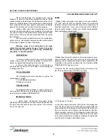
These dishmachines are equipped with vacuum
breakers to serve as back-flow prevention devices. ASSE
requirements specify what type of back-flow prevention is nec-
essary on dishmachines. Vacuum breakers, unlike air gaps,
have certain parts that have specific tolerances and design
aspects that must be met in order to function properly.
Jackson offers repair kits for replacing some of the
wear items associated with vacuum breakers which will allow
you to save money in that replacement of these parts can take
place
without
removing the vacuum breaker from the plumb-
ing assembly.
The instructions provided here are for maintenance
personnel only. Unauthorized persons should not attempt any
of the steps contained in these instructions.
Warning: many of the instructions and steps
within this document require the use of tools. Only autho-
rized personnel should ever perform any maintenance
procedure on the dishmachine!
PREPARATION
1. Power must be secured to the unit at the service
breaker. Tag or lock out the service breaker to prevent acci-
dental or unauthorized energizing of the machine.
2. Ensure that incoming water to the machine is
secured either by use of a shut-off valve or disconnecting the
incoming water line.
TOOLS REQUIRED
The following tools will be needed to perform this
maintenance evolution:
1. Small flathead screwdriver
2. Needle nose pliers
TIME REQUIRED
It is estimated that it will take (1) person twenty min-
utes to perform this task, not including all of the items indicat-
ed in the section entitled “PREPARATION”.
IMPORTANT NOTES
1. Read these instructions thoroughly before
attempting this maintenance evolution. Become familiar with
the parts and what actions need to be taken. This will save
time in the long run!
STEPS
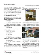
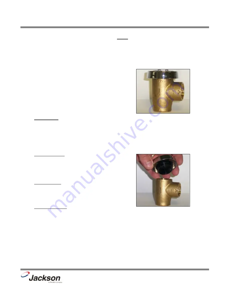
1.
Note:
These instructions only apply to vacuum breakers
(1/2” NPT and 3/4” NPT) as pictured below. The repair kits
indicated in these instructions will only work on those style of
back-flow preventers. If you have a machine with a different
style of vacuum breaker, contact your Jackson representative
about replacement components.
2.
Note:
Even though the photos in these instructions show a
vacuum breaker that has been removed from the plumbing
assembly, these maintenance steps could be performed with
it installed so long as the requirements in the section entitled
“PREPARATION” have been met.
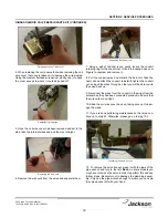
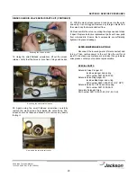
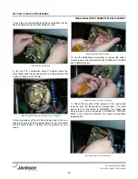
3. Remove the top cap by gripping firmly and turning to the
left. The cap should come off after a few turns.
4. Set the cap to the side.
5. Using the needle nose pliers, gently lift out the plunger and
set to the side. Examine the brass seating surface inside the
vacuum breaker. The plunger is required to sit flat on this sur-
face so it must be free of defects, imperfections and the like.
If there is debris, remove it. If it is chipped or cracked then the
vacuum breaker must be replaced. Failure to do so may result
in the vacuum breaker not working according to its design and
could result in damage to the dishmachine.
SECTION 5: SERVICE PROCEDURES
VACUUM BREAKER REPAIR PARTS KIT
Vacuum breaker
Removing the cap
Summary of Contents for 200B
Page 2: ......
Page 6: ...1 SECTION 1 SPECIFICATION INFORMATION...
Page 10: ...5 SECTION 2 INSTALLATION OPERATION INSTRUCTIONS...
Page 16: ...11 SECTION 3 PREVENTATIVE MAINTENANCE...
Page 18: ...13 SECTION 4 TROUBLESHOOTING SECTION...
Page 21: ...16 SECTION 5 SERVICE PROCEDURES...
Page 32: ...27 SECTION 6 PARTS SECTION...
Page 54: ...49 SECTION 7 ELECTRICAL SCHEMATICS...
Page 57: ......


