

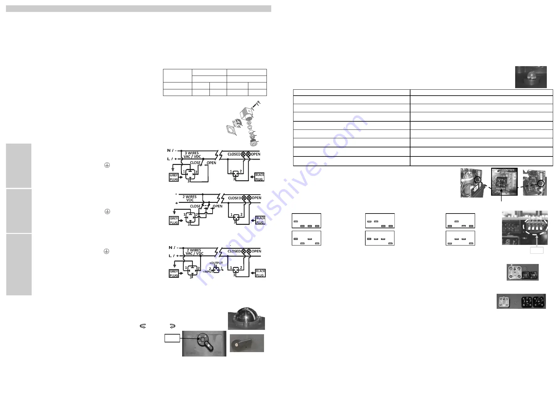
The power supply is connected to the grey “A” DIN plug (Fig.5).
Neutral/negative PIN 1 + Phase/positive PIN 2 - Power supply
Earth/ground connection - Flat PIN on top.
Input/output signal is connected to the black “B” DIN plug (Fig.5).
Negative PIN 1 + positive PIN 2 = Input signal
Negative PIN 1 + positive PIN 3 = Output signal
The volt free connection - black “C” DIN plug (Fig.5).
Common PIN 1 + PIN 2 = Close position confirmation
Common PIN 1 + PIN 3 = Open position confirmation
The power supply is connected to the grey “A” DIN plug (Fig.4).
Negative PIN 3 + Positive PIN 2= Close actuator
Negative PIN 2 + Positive PIN 3= Open actuator
Earth/ground connection - Flat PIN on top.
The volt free connection (conf. of position) black “C” DIN plug
(Fig.4)
Common PIN 1 + PIN 2 = Close confirmation of position
READ THESE INSTRUCTIONS BEFORE CONNECTING THE ACTUATOR. DAMAGE CAUSED BY NON COMPLIANCE
OF THESE INSTRUCTIONS IS NOT COVERED BY OUR WARRANTY.
J4C
Electric actuators operate with the use of live electricity. It is recommended that only qualified electrical engineers be allowed to con-
nect or adjust these actuators.
1.- VOLTAGE
All our actuators model S20 to S300 are ready to work from 24-240VDC/VAC.
All our actuators model B20 to B300 are ready to work at 12 VDC/VAC
ONLY
.
2.- ELECTRICAL CONNECTORS:
Warning:
Before connecting ensure that the voltage to be applied to the actuator
is within the range shown on the identification label. The supplied electrical con-
nectors, used to connect to the actuator are DIN plugs. Ensure the diameter of
cable to be used conforms to the maximum and minimum requirements of the
DIN plugs to maintain water tightness (Fig.1).
Warning:
Ensure that the square rubber seal is in place when fixing each DIN plug to the
actuator. Failure to do so could allow water ingress and damage caused by this installa-
tion error will invalidate any warranty. The DIN plugs are fixed to their respective bases
on the actuator housing with a screw. Do not over tight the screw when assembling (Max.
0.5 Nm ).
J4C 20 TO 300 INSTALLATION INSTRUCTIONS J4CV02
3.- LOCAL VISUAL POSITION INDICATOR:
All
J4C
actuators are supplied with a local visual position indicator comprises a black base with a yellow insert
that shows, both the position and direction of rotation. (Fig.6). The open and close positions have the following
logos molded into the top cover OPEN 90 and CLOSE 0. Opening = Closing =
ACTUATOR OPERATIONAL STATUS
LED STATUS
Actuator without power being supplied
OFF
Actuator with power being supplied
OPEN=GREEN / CLOSE= RED
Actuator , moving from ….. .to …., (flashing led)
FROM OPEN TO CLOSE=RED, ORANGE/ FROM CLOSE TO OPEN=GREEN, ORANGE
Actuator w torque limit function on, moving from …. To …..,(flashing led)
FROM OPEN TO CLOSE=RED, OFF / FROM CLOSE TO OPEN=GREEN, OFF.
Actuator in MANUAL mode
(ORANGE, OFF) SYMMETRIC SQUENCE
Actuator without power and working with the BSR system. MAX. 3 min-
utes
BSR NC = RED, OFF / BSR NO = GREEN, OFF
Battery protection. Danger - The battery needs recharging. BSR disabled.
(ORANGE, OFF) ASYMMETRIC SEQUENCE
Actuator with DPS
STOP=BLUE/ OPENING=BLUE, GREEN / CLOSING=BLUE, RED
When
“MAN”
function is selected:
1-The electronic system cuts the power to the motor after a few seconds.
2-The mechanical connection between the motor and the output shaft is disconnected.
3-The desired position can be achieved by using the manual override lever or the hand wheel.
4-There are two ways to re-active the motor after being isolated whilst in “MAN” position:
a)
With the actuator in “MAN” function, turn the hand wheel to one of the end positions (open or close). If the end position switch is activated the motor
stops. Now change the manual override from “MAN” to “AUTO” , and the actuator is ready to operate automatically again.
b)
Change from “MAN” mode to “AUTO”. Deactivate the supply voltage for a few seconds which resets the actuator and it could operate automatically
again.
ATC
is in charge of the automatic control of inner temperature. It is ON while the actuator is connected to the power supply. Therefore, we strongly
recommend to maintain the power supply connected to the actuator, otherwise the ATC system would remain disconnected.
5.- EXTERNAL LED LIGHT STATUS:
The LED status light provides visual communication between the actuator and the user.
The current operational status of the actuator is shown by either solid lit, or different flashing sequences of the LED light:
6.- BSR - NC/NO set-up:
In case of an electrical failure, the actuator which is fitted with the BSR plug-in failsafe system,
will go to the predetermined position: NO (Normally Open) or NC (Normally Close).
Set up by using the SELDIR Jumper (Fig.9): NC: jumper on / NO: jumper off.
7.- DPS :
Use the configuration you need by moving the DIPs:
In order to set the actuator up, use the DIPs shown in picture .
External adjustment
-
B
plug - Connect a cable between PIN 1 (on the right side) and PIN Earth (on the bottom) (Fig. 11).
-
A
plug - Connect voltage to the actuator in the following way: VAC: PIN1 (neutral) and PIN2 (phase).
VDC: PIN1 (negative) and PIN2 (positive).
*VERY IMPORTANT: BEFORE CONNECTING “
A
” PLUG TO THE ACTUATOR, CHECK THAT THE
VOLTAGE IS THE SAME AS THE ONE SPECIFIED ON THE ID LABEL (CARTER).
-
B
plug - Disconnect the cable between PIN 1 (on the left side) and PIN Earth (on the bottom).
The actuator will make a complete maneuver.
The actuator is ready to connect the (4/20mA or 0/10V) signal to the
B
plug.
8.- KITS BSR / KIT DPS
To make the KITS assembly, follow the steps on the instruction manual enclosed inside each kit.
9.- MOUNTING TO COMPONENT BEING ACTUATED (Ex:1/4 turn valve).
It is vital that the mounting kit used to connect the electric actuator to the component (ex: valve) is correctly manufactured and assembled. The mounting
bracket’s holes must be drilled to ensure that the centerline of the actuator’s drive is perfectly in line with the component’s drive-centerline, and that the
drive coupling/ adaptor rotates around this centerline. The mounting holes of the actuator conform to ISO 5211, and the female output drive conforms to
DIN 3337.
We strongly recommend that valves/components to be actuated that have ISO 5211 compliant top works are used wherever possible as it greatly assists
in ensuring the concentricity of mounting the actuator to the valve.
The male square end of the drive coupling MUST NOT be longer than the maximum depth of the actuator female output drive when the assembly is
bolted together.
Failure to comply with these instructions will cause uneven wear and dramatically reduce the working life of the valve and actuator.
In case of a power supply failure, the actuator would stop in the position it were at this moment. When the power supply is reestablished, the actuator
would keep on working following the prior direction.
VERY IMPORTANT:
Check that any object are blocking the valve (damper, etc.). Connect the actuator, following the connection diagram on the label
of the actuator. We recommend that the actuator has an independent system of fuses, which could protect the actuator against other electrical devices.
CONNECTOR
SMALL BLACK
BIG GREY or BLACK
DIN43650/C
EN175301-803 FORM A
MODEL
min Ø
máx. Ø
min Ø
máx. Ø
J4C 20 a 300
5mm
6mm
8mm
10.5mm
FIGU
R
E
1
FIGU
R
E
2
ON/OFF
VAC
Electrical connection: All models.
FIGU
R
E
4
A
C
ON/OFF
VDC
FIGU
R
E
5
A
C
B
POSITIONER
VAC
VDC
* For other connection options please contact the vendor.
4.- EMERGENCY MANUAL OVERRIDE FACILITY:
The
J4C
has 2 operating modes, automatic and manual , the required mode is selected by
using a lever on the lower half of the actuator housing (Fig 7).
The 2 positions are marked:
AUTO = Automatic operation
MAN = Manual operation
Warning:
Do not remove the selector lever securing screw, as this will allow its internal mechanism to become loose and will cause irreparable damage
to the actuator’s gearbox. Removing this screw will invalidate the warranty.
When
“AUTO”
position is selected:
The hand wheel, of models 20,35,55, and 85 rotates automatically, it is very important not to block it, otherwise the actuator could suffer unrepairable
damages.
FIGU
R
E
8
FIGU
R
E
1
1
1
2
3
4
1
2
3
4
1
2
3
4
1
2
3
4
1
2
3
4
1
2
3
4
4/20 mA
NC
4/20mA
NO
0/10 V
NC
0/10 V
NO
1/10 V
NC
1/10 V
NO
FIGU
R
E
1
0
DIPs
1 Gasket
2 Terminal strip
3 Cable fixing screws
4 Housing
5 Washer
6 Grommet
7 Gland - nut
8 Fixing screw
9 Washer
10 Gasket
1
2
3
4
5
6
7
9
8
10
FIGU
R
E
3
A
C
FIGU
R
E
6
B
C
A
J4C 140 to 300 COVER
B
A
C
J4C 20 to 85 COVER
FIGU
R
E
7
J4C 140 to 300
Screw
J4C 20 to 85
(B)MAN
(A)AUTO
(B)MAN
(A)AUTO
The power supply is connected to the grey “A” DIN plug (Fig.3).
Neutral PIN 1 + Phase PIN 2 = Close actuator
Neutral PIN 1 + Phase PIN 3= Open actuator
Earth/ground connection - Flat PIN on top.
The volt free connection (conf. of position) black “C” DIN plug (Fig.3)
Common PIN 1 + PIN 2 = Close confirmation of position
Common PIN 1 + PIN 3 = Open confirmation of position
FIGU
R
E
9
J4C 20 to 85
J4C 140 to 300
Jumper SELDIR


