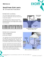
IXOM GridBee GF1250PWc Owner'S Manual Download Page 5

Permit-Required 

Confined Spaces

A confined space has limited openings for

entry or exit, is large enough for entering and 
working, and is not designed for continuous 

worker occupancy.  Confined spaces include 

underground reservoirs, ground storage tanks, 
elevated tanks, silos, manholes, and pipelines.

Confined Space Tips


 Do not enter permit-required confined spaces 

  without being trained and without having a
  permit to enter. 

 Review, understand and follow employer’s

  procedures before entering permit-required

  confined spaces and know how and when

  to exit. 

 Before entry, identify any physical hazards. 

 Before and during entry, test and monitor for 

  oxygen content, flammability, toxicity or

  explosive hazards as necessary. 

 Use fall protection, rescue, air monitoring, 

  ventilation, lighting and communication 
  equipment according to entry procedures. 

 Maintain contact at all times with a trained 

  attendant either visually, via phone, or by
  two-way radio.  This monitoring system
  enables the attendant and entry supervisor
  to order you to evacuate and to alert
  appropriately trained rescue personnel to
  rescue entrants when needed. 

Refer to 29 CFR 1910.146 for complete 
regulations set by OSHA.  Refer to your state's 
regulations if your state established and operates 
their own safety and health programs approved 
by OSHA.

Protect Yourself 

It is important that you comply with all relative 
OSHA and local regulations while installing 
and performing any maintenance to the mixer 
circulation equipment.  

Key OSHA Compliance Standards that must
be followed (and not limited to) are:

• 

1910.146 Permit-required confined spaces

• 

1910.147 Lockout/Tagout

• 

1926.500 Fall Protection

Fall Protection Tips


 Identify all potential tripping and fall hazards 

  before work starts. 

 Look for fall hazards such as unprotected

  floor openings/edges, shafts, open hatches,

  stairwells, and roof openings/edges. 

 Inspect fall protection and rescue equipment

  for defects before use. 

 Select, wear, and use fall protection and

  rescue equipment appropriate for the task. 

 Secure and stabilize all ladders before

  climbing. 

 Never stand on the top rung/step of a ladder. 

 Use handrails when you go up or down stairs. 

 Practice good housekeeping. Keep cords, 

  welding leads and air hoses out of walkways
  or adjacent work areas.

Refer to 29 CFR 1926.500 for complete 
regulations set by OSHA.  Refer to your state's 
regulations if your state established and operates 
their own safety and health programs approved by 
OSHA.

Lockout Tagout

When the On/Off switch is in the "ON" position, 

the mixer may start up at any time if not already 

operating.  The mixer's On/Off switch can be 

locked out by placing a pad lock thru the door latch 
of the controller after the switch has been turned 

to the "OFF" position.  The On/Off switch is to be 

used as the emergency stop.

©2021 IXOM Watercare Inc. | www.ixomwatercare.com | 866 - 437 - 8076 | [email protected]

Safety

1949_10036_20210428

O&M_GF1250PWc_10110_20210922 - 3

Summary of Contents for GridBee GF1250PWc

Page 1: ...2021 IXOM Watercare Inc www ixomwatercare com 866 437 8076 watercare ixom com O M_GF1250PWc_10110_20210922 GridBee GF1250PWc Owner s Manual...

Page 2: ...le of Contents 10014_20210413 GridBee GF1250PWc Owner s Manual Safety 1 Operation 4 Features 8 Maintenance 14 Electrical 21 Troubleshooting 23 Parts Diagram 26 Dimension Drawing 27 Appendix 28 Technic...

Page 3: ...can avoid hazards by following these safety instructions and applying some ordinary common sense when operating or servicing this unit Keep in mind that full operator attention and alertness are requi...

Page 4: ...tive ELECTRICAL HAZARD WARNING THIS EQUIPMENT CONTAINS HIGH VOLTAGE ELECTRICAL SHOCK CAN CAUSE SERIOUS OR FATAL INJURY ONLY QUALIFIED PERSONNEL SHOULD ATTEMPT PLACEMENT OPERATION AND MAINTENANCE OF EL...

Page 5: ...all relative OSHA and local regulations while installing and performing any maintenance to the mixer circulation equipment Key OSHA Compliance Standards that must be followed and not limited to are 19...

Page 6: ...entle mixing de stratification and surface renewal The GF series GridBee requires a minimal amount of AC grid power The grid provides power to the onboard AC DC power box and motor controller that dri...

Page 7: ...base of the machine can be performed on the reservoir exterior prior to lowering the equipment inside if the hatch has a clear opening of at least 24 inch diameter 60cm A hatch this size or larger wil...

Page 8: ...ne by pushing hose up and all the way up above metal rib See Figure 6 STEP 3 On the other end of the hose place the other hose clamp over the end Fasten hose to the intake box past the metal rib of th...

Page 9: ...LLY ASSEMBLED 2021 IXOM Watercare Inc www ixomwatercare com 866 437 8076 watercare ixom com Small Frame Assembly SB GF1250PWc SB GF1250PWc Assembly Assembly Diagram 10312_20210810 O M_GF1250PWc_10110_...

Page 10: ...on the inside of the tank Motor Controller The motor controller is located near the motor just below the top plate of the Gridbee The motor controller is sealed in line with the electrical cord that r...

Page 11: ...nto the housing of the brushless motor fastening it onto the machine The brushless motor is built to be very durable The housing is constructed of casted aluminum The brushless motor runs very quietly...

Page 12: ...ree to rotate on the shaft If the water should freeze around the machine the freeze sleeve will stand still frozen in by the ice but inside the plastic sleeve the impeller shaft will be turning The im...

Page 13: ...ieve best flow results The distributor dish depth is set at the factory and should not need adjustment after deployment Hose Intake The hose extends from below the dish down to the floor of the reserv...

Page 14: ...is shaped to hug the hose for installation purposes allowing the machine to be installed in a 24 square hatch The floats have a uniquely designed shape to Minimize space when collapsed around the hos...

Page 15: ...nit frame when the float is extended into place by means of boyancy pressure when deployed into the water If the machine is resting in the bottom of an empty tank the GridBee will be supported against...

Page 16: ...irst every time the Machine is inspected or having maintenance procedures performed It is strongly encouraged that anyone working on or near the machine follow these rules Wear a personal floatation d...

Page 17: ...ee points to be used in order to support the weight of the machine and keep it balanced once suspended 500PWc CAUTION DO NOT REMOVE ANY FLOAT ASSEMBLY PINS OR BOLTS WHILE THE MACHINE IS FLOATING IN TH...

Page 18: ...entry Therefore the float assembly were designed to set the machine in the correct depth of water when the machine is deployed There are no adjustments that needed for setting the dish depth After the...

Page 19: ...te and at least 20 seconds This step is easier with two people one counting revolutions and the other keeping track of the time expired STEP 3 Quit counting revolutions and immediately observe how muc...

Page 20: ...al laws and regulations when disposing of any materials collected STEP 5 Once clean place impeller assembly back in place Be sure bottom of impeller shaft fits into the bushing in the dish and that th...

Page 21: ...nd STEP 2 Cover the entire machine including the hose and intake assembly using a heavy duty tarp Be sure to tuck the tarp under the machine to avoid any sand being collected on the machine in the cas...

Page 22: ...not get tangled on any objects STEP 7 The machine is now ready for the tank to be filled with water and be turned On Most customers feel that removing the machine circulation equipment is the best opt...

Page 23: ...NNECTION GRID POWER ONLY 120VAC 60HZ 2 0 AMPS MOTOR CONTROLLER BRUSHLESS DC MOTOR 2021 IXOM Watercare Inc www ixomwatercare com 866 437 8076 watercare ixom com Electrical Electrical Overview GF Series...

Page 24: ...e red light blinking once followed by one yellow blink and one green If you miss this or are unsure you can repeat the previous steps If the update was not successful the red yellow and green lights w...

Page 25: ...BEFORE ENTERING ENCLOSURE IXOM WATERCARE INC STRONGLY RECOMMENDS THAT AN ELECTRICIAN INSTALL A BREAKER SWITCH OR OTHER TYPE OF SWITCH THAT WOULD DISCONNECT AC POWER GOING INTO THE ELECTRONIC CONTROL B...

Page 26: ...otor circuit voltage can be measured off terminal blocks 1 and 2 The proper motor voltage should be approximately 45vDC Brain Board voltage should be approximately 12vDC and can be measure as shown to...

Page 27: ...PPLY LED SOLID GREEN LIT SOLID GREEN NOT LIT ERROR CODES 12 VDC ON 12 VDC OFF 12 VDC POWER SUPPLY LED SOLID GREEN LIT SOLID GREEN NOT LIT Source Power Circuit 120 VAC Control Circuit 12 VDC Motor Powe...

Page 28: ...14013022 Motor Control Cord 04 PN 20504700 Brushless Motor 05 PN 100161 Control Box with Brainboard 06 PN 26060840 8 x 40 Hose NSF White 07 PN 18010015 Distributor Dish 08 PN 26283008 Intake Box Assem...

Page 29: ...21 IXOM Watercare Inc www ixomwatercare com 866 437 8076 watercare ixom com Dimension Drawing 1250PWc Dimension Drawing SB GF Series Small Frame Mixers 789_10242_20210730 O M_GF1250PWc_10110_20210922...

Page 30: ...Technical Data Sheets 2021 IXOM Watercare Inc www ixomwatercare com 866 437 8076 watercare ixom com Appendices Appendix Additional Component Information 10576_20210611 O M_GF1250PWc_10110_20210922 28...

Page 31: ...Intake Hose 20 to 60 feet 6 to 18 m available in 8 inch 20 cm diameter X 20 feet 6 m sections Intake Assembly at Bottom of Hose Rectangular intake with openings around perimeter Intake Depth Adjustme...

Page 32: ...e function 3 two bytes of register address two bytes of number of points and the CRC The address of the holding registers can be found in the table below The format of the reply consists of the GridBe...

Page 33: ...able 7 NA Not Applicable 8 NA Not Applicable 9 Visual Status Indicator This value gives an indication of the GridBee controller health blink indicator During normal operation the following values will...

Page 34: ...GPS Comm Motor Comm and Analog OOR Error For Customer Service contact Ixom Watercare Inc Office and Service Center at 866 437 8076 Table 4 Visual Status Indicator Register Address 9 Priority Levels Pr...

Page 35: ...y S N PART A 36 2 4 V 20014700 1234XXXX 7 Motor Specifications Size 7 inch 18cm diameter X 4 inch 10cm height Weight 25 lb 12 kg Housing Sealed 356 T6 Cast Aluminum Shaft Stainless Steel V ring seal T...

Page 36: ...e factory s service crews performed the original on site placement and startup then this warranty also includes labor Where labor is included in lieu of sending a factory service crew to the site for...

Page 37: ...the world Contact us today to discuss your water quality and service needs EVERYONE DESERVES GREAT CUSTOMER SUPPORT IXOM Watercare earns customer trust with unparalleled service start to finish Every...

Reviews: