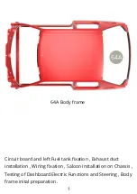
IXO 64A Manual Download Page 2

63N

61F

63O

63P

49F

22A

63P

63O

63N

44H

2

Lead one by one , through square opening in 

22A Chassis panel

  the following 

wires : 

63N G Cable

 ( 

white

-

gray

 ), 

63O M Cable

 ( 

green

yellow

 ) , 

63P S Cable


red

-

green

 ) , 

61F J Cable

 ( 

red

-

green

 ) and 

49F B Cable

 ( 

yellow

 - black

 ) . 


Fit the plugs of 

63N G Cable

 ( 

white

-

gray

 ), 

63O M Cable

 ( 

green

yellow

 ) and 

63P S Cable

 ( 

red

-

green

 ) into respective letter marked

sockets on 

44H Circuit board .


Summary of Contents for 64A

Page 1: ...Body frame Circuit board and left Fuel tank fixation Exhaust duct installation Wiring fixation Saloon installation on Chassis Testing of Dashboard Electric Functions and Steering Body frame inital pr...

Page 2: ...panel the following wires 63N G Cable white gray 63O M Cable green yellow 63P S Cable red green 61F J Cable red green and 49F B Cable yellow black Fit the plugs of 63N G Cable white gray 63O M Cable g...

Page 3: ...61F J Cable red green and 49F B Cable yellow black into respective letter marked sockets on 44H Circuit board Fit 44A Left side fuel tank to 22A Chassis panel by turning it over blue arrows and slippi...

Page 4: ...langes to 22A Chassis panel with two BM screws Fix 36G Left parking brake cable pointed by red arrow on previous illustration with 44C Clamp to 44A Left fuel tank using AP screw Fit 44B Heatshield on...

Page 5: ...ld are installed Prior to installing the Exhaust duct take note of first two attachment points 41A Front pipe goes under 16B Subframe bar further explained on next two illustrations and 41D Catalytic...

Page 6: ...16B 22A 6I 6I 16B 22A 41A 6 Note 6I Exhaust manifold flange niche and fit 41A Front pipe end into it passing down under 16B Subframe bar top and bottom illustrations...

Page 7: ...22A 41D 22A IP 7 Fit 41D Catalytic converter top peg into 22A Chassis panel nest and fix from above with IP screw top and bottom illustrations...

Page 8: ...42E 42D CM CM 42C 8 Fit 42C Exhaust silencer to 42E Exhaust mount and secure it with 42D Clip and two CM screws top and bottom illustrations...

Page 9: ...41H E Cable gray white 41E Speaker cable C red green and 41I K Cable red black as shown and fix with three 63Q Tapes to 22A Chassis panel Group together cables mentioned on previous illustration plus...

Page 10: ...44I 63Q 63Q 63Q 22A 10 Lead 44I H cable red green to both sides of 22A Chassis panel 44J F cable blue white to right side and fix at the sides with two 63Q tapes Cables arranged for Saloon and Chassi...

Page 11: ...18A 18B 11 Undo two AM screws and remove 18A Joint link from 17G Shaft fork above illustration to fit it to 18B Shaft fork and fix with two AM screws illustration below This arrangement will facilita...

Page 12: ...assis lead 17G Shaft through square opening in 49A Pedals panel and before engaging the shaft fork with 18A Joint link check the forward alignment of Front wheels blue arrow on illustration below and...

Page 13: ...IP 45A 22A 13 After the above described alignment finally engage 17G Shaft fork with 18A Joint link and fix from left and right sides with two AM screws Fit 45A Saloon floor to 22A Chassis panel and f...

Page 14: ...er screw red arrow and open it blue arrow Fit two AAA size batteries into 43A Battery compartment of Right side Fuel tank observing and polarities greenarrows Put ON battery compartment swithch red ar...

Page 15: ...l blue arrow to see front wheels response Press 63L Rear fog lamp knob to observe Instrument panel back light Press 63K Rear screen heater knob to hear the Engine sound Press 63J Hazard warning knob t...

Page 16: ...64A 16 Saloon mounted on Chassis Undo four screws to remove two spacer bars from 64A Body frame...

Page 17: ...17 Final views...

Page 18: ...18 Assembly drawings...

Page 19: ...19...

Reviews: