TP-CU3-ZD, -DC Gig Zero Delay
Quick Install Guide
913-2114-01 Rev B 1/15
TP-CU3, -DC 10/100/1000BaseT Tap
Page 1: ...TP CU3 ZD DC Gig Zero Delay Quick Install Guide 913 2114 01 Rev B 1 15 TP CU3 DC 10 100 1000BaseT Tap...
Page 2: ...DFARS 252 227 7013 and FAR 52 227 19 Ixia the Ixia logo and all Ixia brand names and product names in this document are either trademarks or registered trademarks of Ixia in the United States and or o...
Page 3: ...ntent 4 TP CU3 ZD and TP CU3 Overview 5 Step 1 Rack Mount Tap 7 Step 2 Connect AC Power 9 Connect DC Power 10 Step 3 Configure the DIP Switches 11 Step 4 Connect to the Network 14 Step 5 Connect to th...
Page 4: ...d power supplies 12VDC 3 3A 2 5mm IEC C13 2 Power cords and power supplies 12VDC 1 5A 2 5mm IEC C13 TP CU3 only Retainer clip not included with DC models 3 CAT 5e 4 pair purple cable 3 meter RJ45 1 CA...
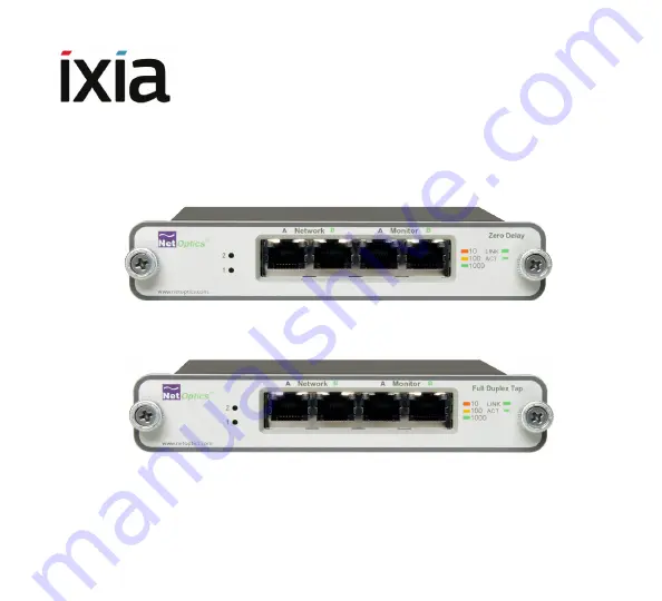
Page 5: ...rrent power source LED illuminates white Link Activity Indicator Located in the upper right corner If a good link is established the LED lights up The LED flashes when there is activity 10 100 1000 In...
Page 6: ...Rear Panel DC power model TP CU3 DC Figure 5 Rear Panel DC power model TP CU3 ZD DC Power DC Jacks Retainer Clip DIP Switch 1 3 4 5 6 7 8 2 For use with 48 only Terminal Blocks DIP Switch 1 3 4 5 6 7...
Page 7: ...ollowing 1 Remove the panel and screws from the shipping bag 2 Screw the panel onto the rack 3 Slide the switches in place in the rack See Figure 6 See Figure 7 if you ordered the 12 Slot version 4 Fa...
Page 8: ...8 Figure 7 Tall 12 Slot Version...
Page 9: ...d to a power source See Figure 8 2 For redundancy plug the other power cord to the other connector Plug the other end to a source independent from the first power source The second power supply is ava...
Page 10: ...or convenience when connecting the power wires Just pull to unplug the removable part and push it back in to reconnect it To connect the power wires insert a wire into a socket and tighten the screw t...
Page 11: ...ap except for Switch 1 Link Fault Detect which applies only to the Network Ports If you use fixed settings connected devices must match the settings you select for the Tap If you use Auto negotiation...
Page 12: ...Half duplex If switch 2 is ON this switch is ignored 7 Reserved 8 ON OFF Up position The backup battery is not connected Down position The backup battery is connected The unit is shipped with this swi...
Page 13: ...wn position After you connect power make sure the power is ON for 12 hours to fully charge the backup battery In the event of a power outage the Zero Delay Tap can remain powered for 3 to 5 hours with...
Page 14: ...rk Port B to the appropriate switch server or router using one of the supplied purple CAT5e cables 3 Verify that the Tap Network Ports are cabled in line between two devices 4 Verify the link LEDs ill...
Page 15: ...ing device using one of the supplied purple CAT5e cables 2 Connect Monitor Port B to the appropriate port on the monitoring device using one of the supplied purple CAT5e cables Figure 12 Connecting to...
Page 16: ...E mail support emea ixiacom com India 91 80 49396410 E mail support india ixiacom com Japan 81 3 5326 1980 E mail support japan ixiacom com APAC 65 6332 0126 E mail support asiapac ixiacom com China 4...