background image

INSTALLATION DIRECTIVE

MAY 2006

10

V08 EnT M75 - M11 - M12 

3.  INSTALLATION OVERVIEW 

Figure 

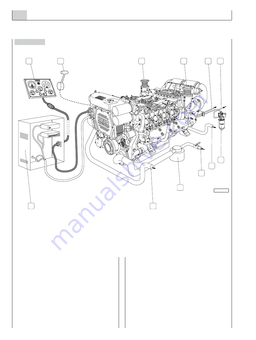
The  figure  shows  the  set  of  components  of  an  installation, 

including those supplied with the engine equipment, standard 

or optional, and those supplied or produced by the yard.

It  provides  a  comprehensive  picture  of  the  operations 

required to install the engine.

Components arrangement and illustrations are not binding 

but merely indicative, subject to the choices made by yard 

engineers  according  to  their  skills,  available  spaces  and  the 

prescriptions set out herein.

05_003_V

1

2

3

4

5

6

7

8

9

10

11

3

1. Main instrument panel - 2. Throttle actuator - 3. Exhaust gas outlet - 4. Fuel return pipe to tank - 5. Fuel suction pipe - 

6. Prefilter with priming pump - 7. Sea water outlet from air/water heat exchanger - 8. To the filtered sea water intake - 

9. Sea water decanter filter - 10. Sea water outlet from water/water heat exchanger - 11. Electrical system cabinet.

Summary of Contents for V08 ENT M11

Page 1: ...VECTOR V08 ENT M75 V08 ENT M11 V08 ENT M12 V 8 MODEL DIESEL CYCLE FOR MARINE APPLICATIONS INSTALLATION DIRECTIVE MAY 2006 EDITION T E C H N O L O G I C A L E X C E L L E N C E ...

Page 2: ...rking life Exclusive use of IVECO Original Parts is a necessary condi tion to maintain the engine in its original integrity Tampering making modifications and using non original parts can jeopardize the safety of boat engineers and users To obtain spare parts you must indicate Commercial code serial number and indications shown on the engine tag Part number of the spare as per spare part catalog T...

Page 3: ...1 5 TECHNICAL DATA FOR INSTALLATION 12 6 IDENTIFICATION DATA 14 7 FUEL LINE 15 8 ELECTRICAL EQUIPMENT 17 9 MAIN ANALOG INSTRUMENT PANEL 26 10 SECONDARY ANALOG INSTRUMENT PANEL 30 11 DRILLING PLANS FOR ANALOG PANELS 31 12 CUSTOMIZED INSTRUMENT PANEL 32 13 SENSORS FOR DETECTION AND INSTRUMENT PANEL SIGNALLING 34 14 PREPARING THE ENGINE FOR FIRST START UP 37 15 TESTS BEFORE THE FIRST START UP 37 16 F...

Page 4: ... with the IVECO MOTORS directive in terms of length type of conductor location clamping connection of the shielding and earth braids o To avoid any interference the wiring harnesses of the different on board electronic devices must follow diffe rent paths from those of the engine electronic systems o Do not connect any extraneous user device to the engi ne electrical equipment o Do not energize th...

Page 5: ...rough unfiltered lines o Do not clean the engine and its parts with corrosive or abrasive detergent substances to avoid compromising the integrity of electrical connections o The engine fluids and air coolant and oil filters discar ded after use must be properly stored and delivered to appropriate collection centres Long engine inactivity periods Before long periods of inactivity ready the engine ...

Page 6: ... pressure injection pump 4 Cooled turbo charger 5 Exhaust gas outlet 6 Lever for switching fuel filters 7 Engine coolant level sensor 8 Water water heat exchanger 9 Pressurization cap for coolant tank 10 Sea water pump 11 Engine coolant pump 12 Fuel filters 13 Lifting padeyes 14 Cylinder 1 electro injector 15 Cooled exhaust manifold 16 Cylinder 4 electro injector 17 Lifting padeyes 18 Air sea wate...

Page 7: ...ake air filter 8 Air sea water heat exchanger 9 Lifting padeyes 10 Cylinder 8 electro injector 11 Lubricating oil dipstick 12 Lubricating oil refill cap 13 Cylinder 5 electro injector 14 Cooled exhaust manifold 15 Lifting padeyes 16 Location of the low pressure fuel transfer pump 17 Tap and fitting for lubricating oil transfer 18 Sacrificial anode 19 Lubrication oil transfer electrical pump 20 Sea...

Page 8: ...lves 3 Air sea water heat exchanger 4 EDC Electronic Central Unit 5 Exhaust gas outlet 6 Fuel inlet and outlet fittings 7 Crankshaft sensor 8 Cooled turbo charger 9 Lifting padeyes 10 Cooled exhaust manifold 11 Cylinder 8 electro injector 12 Lubricating oil dipstick 13 Lubricating oil refill cap 14 Cylinder 5 electro injector 15 Lifting padeyes 16 Sea water intake ...

Page 9: ...t 2 EDC Electronic Central Unit 3 Air sea water heat exchanger 4 Location of thermostatic valves 5 Fuel filters 6 Lifting padeyes 7 Cylinder 1 electro injector 8 Cooled exhaust manifold 9 Cylinder 4 electro injector 10 Lifting padeyes 11 Cooled turbo charger 12 Sacrificial anode placed on the air water heat exchanger ...

Page 10: ...angement and illustrations are not binding but merely indicative subject to the choices made by yard engineers according to their skills available spaces and the prescriptions set out herein 05_003_V 1 2 3 4 5 6 7 8 9 10 11 3 1 Main instrument panel 2 Throttle actuator 3 Exhaust gas outlet 4 Fuel return pipe to tank 5 Fuel suction pipe 6 Prefilter with priming pump 7 Sea water outlet from air wate...

Page 11: ...d to install a suitably dimensioned and easily replaced zinc anode The engine sea water line was provided by the manufacturer with protection anodes to be replaced periodically The rubber hoses positioned along the pipeline shall be suffi ciently rigid not to create choked areas caused by crushing 1 Engine pre heating If the engine usage profile requires immediate delivery of power at the highest ...

Page 12: ...0 Riser outer diameter mm inches Dry exhaust outer diameter mm inches 105 4 105 4 105 4 Diameter of circumference of distance between 6 locking holes mm inches 127 5 127 5 127 5 Fuel supply Low pressure pump delivery at maximum rpm l h 400 400 400 Fuel temperature to allow maximum power C 70 70 70 Inner diameter intake pipe mm 14 14 14 Inner diameter return pipe mm 8 8 8 Thread on prefilter fittin...

Page 13: ...andard dipstick degrees 360 0 10 0 10 0 10 Power takeoffs optional 2 race front pulley for V belts Reference diameter mm Race dimension mm Power available per belt at 650 rpm kW CV Power available per belt at 1300 rpm kW CV 2 race front pulley elastic joint for flange Torque available in engine axis Nm kgm 2 race front pulley elastic joint for crankshaft Torque available in engine axis Nm kgm Radi...

Page 14: ...ne identification data are stenciled on a tag positioned over the engine coolant tank Viale dell Industria 15 17 20010 Pregnana Mil se MI ITALY ENGINE TYPE ENGINE DWG ENGINE S N COMMERC TYPE VERSION POWER SET CODE HOMOLOGATION No ENGINE FAMILY POWER KW AND SPEED RPM YEAR OF BUILD S p A 04_039_C 05_002_V ...

Page 15: ...d with vents to avoid exceeding an internal pressure of 5kPa 0 5 m of H2 O column their shape and the suction assembly must be such as to assure a suction at the maximum longitudinal and transverse inclina tion allowed for the boat with a residual quantity of fuel oil considered reserve The suction inlet should be positioned in such a way as to avoid taking in sludge The return flow must be in suc...

Page 16: ...pressure valve 11 Low pressure recirculation duct 12 Fuel tank 13 Prefilter 14 Manual priming pump 15 Vent fitting 16 Recirculation valve for low pressure pump 17 Low pressure mechanical feed pump 18 By pass valve for low pressure pump 19 Lever for switching filters 20 Fuel filters 21 Filter exclusion valves 1 Fitting for fuel outflow to the tank 2 Fitting for for fuel inflow from prefilter 3 Pref...

Page 17: ...ect the accumulator to the engine wire harness The connection of the J3 connector enables the electric connection of the control module to the lubricating oil pouring pump The JC connector is set for the connection to the emergency stop button 05_013_V 4 5 1 18 3 17 2 16 15 14 13 12 7 11 10 9 8 6 1 Indicator and control panel 2 Electronic Central Unit 3 Power line for electric starter motor and al...

Page 18: ...R BOX ALTERNATOR ELECTRIC STARTER MOTOR RELAY BOX BATTERY EDC ELECTRONIC CENTRAL UNIT INDICATIONS AND ALARMS SENSORS 05_006_V 1 1 2 5 3 4 6 V08 ENT M INDICATIONS AND ALARMS SENSORS THROTTLE POSITION SENSOR EDC COMPONENTS ELECTRO INJECTORS 1 Connector for instrument panel connection wire harness 2 Engine wire harness 3 Connector for control unit of the lubrication oil transfer electrical pump 4 Con...

Page 19: ...cal pump JF1 JF2 Relay box JG Lubrication oil transfer electrical pump control unit JG1 Pre lubrication electrical pump control unit K K1 Clogged air filter sensors for alarm M Sensor to detect water in the fuel prefilter for alarm MM Electric starter motor O O1 Exhaust gas temperature sensors for gauge P Combustion air temperature sensor for EDC PA Throttle position sensor PF Rail pressure contro...

Page 20: ...f the electrical starter motor realized with a conductor having a cross section of at least 50 mm2 o C Connection between the 30 terminal of the alter nator to the positive B terminal of the electric starter motor to close the power supply and recharge circuit of the battery realized with a conductor having a cross section of at least 50 mm2 o D Connection between the B terminal of the alter nator...

Page 21: ...ernator Technical data Nominal voltage 24 V Nominal current 90 A Terminal connection B M8 x 1 25 tightening torque 12 5 Nm 20 Terminal connection B M6 x 1 tightening torque 6 0 Nm 20 B 24 V Power supply output terminal B 0 V Power supply output terminal S Sense Reference voltage of battery charge status connected to B terminal or to be con nected to the positive pole of the battery in case of remo...

Page 22: ...e power line conductors and verifying recharging effectiveness by measuring voltage across the battery poles For the best control of the battery recharge cabling the line relating to the S terminal of the alternator directly to the positive pole terminal of the battery see figure 17 Figure 17 Figure 16 Connect to positive pole terminal of the starter motor B S IG L 05_073_V B Connect to negative p...

Page 23: ...ton of the maintenance alarm 5 Button for managing acceleration and deceleration 6 Connector for diagnostic instrument 7 Blink code emission LED EDC 8 Signalling LED of maintenance interval expiration 9 Signalling LED for fault engine operating parameters WARNING This shall be installed and anchored in such a way as to dampen the vibrations and stresses occurring when under way and they shall be a...

Page 24: ...ring connector J2 Engine component wiring connector A Ground connection of the ECU The connection of the central electronic unit ECU to the EDC system takes place by means of two 70 way connectors The presence of the two connectors provides for a subdivision of the wire harnesses to distribute the large quantity of conductors and at the same time favour a quicker identification of the lines during...

Page 25: ...upport from the boat mass and then connect the support with the negative battery terminal Figure 22 Throttle lever position sensor After testing the working condition of the linkage adjust the run of the servo components see Chapter 15 o With the throttle at idle setting the potentiometer rod has to be in the resting position o With the throttle at the stop the potentiometer rod has to be in the p...

Page 26: ...panel in installations with out secondary panel do not remove the cap of the JE con nector to avoid compromising the electrical continuity of the systems power supply circuit 1 Coolant temperature gauge TA 2 Revolution counter and hour counter CG 3 Voltmeter V 4 Buzzer SA 5 Indications and alarms module MS 6 Engine oil pressure gauge MO 7 Connector for secondary instrument panel JE 8 On board pane...

Page 27: ...d by the individual lines refer to the electrical diagrams in Chapter 20 1 JB JC Extension wire harness 2 JE JH Extension wire harness 1 2 JC JB 32 47 18 28 45 17 29 44 16 42 43 31 46 30 7 11 12 24 38 1 5 6 13 14 15 4 40 26 27 41 25 39 21 22 36 34 8 9 19 20 33 35 23 37 2 3 10 24 12 40 39 22 38 37 23 36 44 16 13 14 41 26 25 27 15 28 42 43 1 11 4 10 2 3 7 5 17 6 18 35 21 9 20 19 33 8 32 34 47 29 45 ...

Page 28: ...0 11 7 04_234_N Installation In order to drill holes on the area where the panel is to be mounted refer to the dimensions indicated in Chapter 11 Operation of the panel After completing the electrical connections and engine preparation perform the tests required for the first start as described in Chapter 18 Verify the proper operation of the panel proceeding as fol lows o Make sure that the ENGIN...

Page 29: ...ntenance Should it become necessary to replace a panel light remove the lamp holder from the rear part of the instrument see Figure 27A Figure 27A 04_255_N 2 1 Revolution counter calibration 1 Calibration increasing button 2 Calibration decreasing button Verify the indication of the panel revolution counter by com paring it with the one measured with a reference instrument if it differs press the ...

Page 30: ...ws o Make sure that the ENGINE ROOM BRIDGE switch of the Relay Box is in the BRIDGE position then turn the key switch to the first position thus enabling the operation of both panels o Carry out the same tests for the secondary panel as were carried out for the main panel o Disable the secondary panel by bringing the key switch on the main panel to the resting or zero position Testing the engine s...

Page 31: ...11 M12 MAY 2006 11 DRILLING PLANS FOR ANALOG PANELS Figure 30 Figure 31 Dimension in millimetres 225 285 26 4 Ø 4Ø 4 Ø 4 Ø 4 140 200 26 26 4 4 26 4 Main panel 04_022_C 180 240 28 2 80 140 28 28 28 Ø 4 Ø 4 Ø 4 Ø 4 2 2 SecondaryPanel 04_023_C ...

Page 32: ... are provided below indications for IVECO MOTORS indicator instruments are shown in the related wiring dia grams in Chapter 20 JD Connector for indications and alarms module VIEW FROM THE SIDE INTEGRATED IN THE REAR PART OF THE MODULE Figure 34 VIEW FROM THE TERMINAL SIDE OF THE COUPLING SIDE WIRING connector TRIDENT ITT CANNON partTST 24PA00 terminal female part 192990 0050 lid rear part TST24AH0...

Page 33: ...ed fuel filter indication Low ground Open circuit 15 Alternator fault indication High B Low 1 to 3 V 16 Low engine coolant level indication Open circuit Low ground 17 High coolant temperature indication Open circuit Low ground 18 Low engine oil pressure indication Open circuit Low ground 19 Presence of water in fuel indication Open circuit Low ground 20 Overloaded or runaway engine indication Open...

Page 34: ...olled by the float of the coolant tank Operating voltage from 6 to 24 V Condition for high level open Maximum current 2 A not inductive Electrical poles isolated Oil pressure sensor Rheostat component providing the signal for the analog indication of pressure Operating voltage from 6 to 24 V Calibration range from 0 to 10 bar Resistance value at 0 bar 10 Ω 3 5 Ω Resistance value at 2 bar 52 4 Ω Re...

Page 35: ...sure normally open Closing pressure 2 4 0 3 bar Opening pressure 1 8 0 3 bar Maximum current 3 A not inductive Electrical poles isolated Figure 40 Figure 41 Clogged fuel filter sensor Figure 42 Pressure switch providing the signal for the related indica tor when the pressure at the fuel filter inlet is too high Operating voltage from 6 to 24 V Condition at ambient pressure normally closed Opening ...

Page 36: ...n electronic circuit providing the signal for the indica torof the presence of water in the fuel Operating voltage from 12 to 24 V Condition in the absence of water open circuit Closed condition resistance of the liquid 1 MΩ Operating temperature from 20 to 80 C Connections of the sensor detecting the presence of water in fuel 1 M Connector of the engine wire harness 2 Sensor detecting the presenc...

Page 37: ...d 7 Remove from the engine the labels with the inscription ENGINE WITHOUT OIL Although they are extremely important common sense checks such as the exposure of sensitive parts plastics wire harness electronic units etc to heat and those that for years have characterized the quality of the work performed in the yard are not mentioned herein Tests of the proper operation of the engine and the com po...

Page 38: ...aution Never attempt to vent the high pressure system as this is useless and extremely dangerous caution Avoid accurately that fuel comes into contact with the alternator belt Start up procedures 1 Control selector from bridge or engine room 2 Power supply switch of the engine electric circuits 3 Start button from engine room 4 Button for managing acceleration and deceleration The electrical equip...

Page 39: ...ulation becomes much more effective and enables to complete the full range of the engine speed in a overall time of about 20 seconds caution Never operate the BRIDGE ENGINE ROOM switch when the engine is running Once the first start up phase is complete verify that o There are no liquid leaks from the coolant loop pipeline junction hoses o There are no exhaust gas leaks in the hull o In order to c...

Page 40: ...s are detected the sum of the current anomaly code is designated list Each single code is organized in 3 digit numerical blocks with a fixed lighting duration equal to 0 6 s The pauses switch off time have a different duration to distinguish the given type of information pause between blinking of the same digit 0 36 s pause between different digits of the same code 1 5 s pause between different co...

Page 41: ...re stored in the failure memory of the ECU The signalling is available on the relay box only and does not involve any other indications on the instrument panel The stored information are able to be decoded and erasable by the IVECO SERVICE TOOL SHUTDOWN preliminary When the most critical thresholds exceed their normal values it can be enabled the forced engine shutdown The next time the engine is ...

Page 42: ...on sensor anomalous or missing signal 154 Engine oil temperature sensor open circuit short circuit to B or to ground 156 Engine oil pressure sensor open circuit short circuit to B or to ground 157 Rail pressure sensor open circuit short circuit to B or to ground 159 Pressure limiter valve open circuit short circuit 162 Pressure limiter valve irregular mechanic behaviour 162 Fuel temperature sensor...

Page 43: ...possible to obtain from the ECU parameters the fuel injection values by using the IVECO MOTORS tool Fuel temperature Verify that the temperature of the fuel in the low pressure line while underway at full power and with a stable quantity of fuel in reserve does not exceed 70 C A higher value would entail a reduction in engine performance If the ten dency to reach the maximum allowed temperature is...

Page 44: ...e over for about 2 minutes after excluding the operation of the injection system The required operation may be carried out by directly polarizing the terminal 50 of the electric starter motor with positive voltage 24V using a conduc tor prepared for the occasion 5 Nebulize 30 M protective oil at the rate of about 100 g 10 g per litre of displacement in both turbochargers while the engine is turnin...

Page 45: ...INSTALLATIONDIRECTIVE 45 V08 ent m75 M11 M12 MAY 2006 ...

Page 46: ...17 1 11 10 31 32 35 34 33 25 26 29 30 28 27 48 53 52 3 R R 21 28 29 13 13 14 14 18 6 4 13 17 43 44 37 13 7 15 37 18 18 12 12 31 31 35 35 9 3 15 11 20 9 18 10 19 50 JC JA JB BAT BAT AC JF2 K4 DK4 CA K1 K2 DK1 DK2 SW1 DK5 F1 b a K5 PH GH GH GN GN PA JA JF1 JA MM JF2 JA JA JC JB JA JF1 JC JB JA JF1 JF1 JA JB JC J1 M J4 J4 JG1 POP K3 DK3 JA JF2 M TGC JF2 JA SW2 SW3 IGNITION START JF1 JA JF1 JA JB JF1 ...

Page 47: ...er motor MS IVECO MOTORS indications and alarms module O O1 exhaust gas temperature sensors for gauge P combustion air temperature sensor for EDC P1 sound alarm inhibition push button PA throttle position sensor PF rail pressure control solenoid valve PH grid heater PO lubrication oil transfer electrical pump POP pre lubrication electrical pump Electrical equipment component code PR rail pressure ...

Page 48: ...to the main analog instrument panel Indicator lights EDC EDC malfunction SAC presence of water in fuel prefilter SATA coolant high temperature SBLA low coolant level SBPO low oil pressure SCP pre post heating SIFA clogged air filter SIFB clogged oil vapour filter SIFC clogged fuel filter SIFO clogged oil filter SIM expired programmed maintenance interval SP pre lubrication SS alternator fault SSV ...

Page 49: ... 31 32 35 34 33 25 26 29 30 28 27 48 53 52 3 RPM RPM SW5 21 28 29 13 13 14 14 18 6 4 13 17 43 44 37 13 7 15 37 18 18 12 12 31 31 35 35 9 3 15 11 20 9 18 10 19 50 JC JA JB BAT BAT AC JF2 K4 DK4 CA K1 K2 DK1 DK2 SW1 DK5 GG M F1 b a K5 J3 JG D1 JF1 JA JA JB M PH GH GH GN GN PA JA JF1 JA MM JF2 JA JA JC JB JA JF1 JC JB JA JF1 JF1 JA JB JC J1 PO M J4 J4 JG1 POP GG K3 DK3 JA JF2 M TGC JF2 JA SW2 SW3 IGN...

Page 50: ... SW2 IGNITION JF1 JA JF2 21 E4 2 1 38 46 28 2 1 E5 E6 2 1 39 47 29 2 1 E7 E8 2 1 6 BAT 6 BAT 1 62 61 J2 J1 1 2 PF 61 65 1 18 14 U P A B C A B C A B C AP 85150 AC 37 45 2 1 E3 48 49 2 1 B 58 59 2 1 C 36 44 20 2 1 E1 E2 2 1 35 P 33 F 34 A 32 S 3 24 2 U P 1 2 3 PR 41 40 U P H 42 25 U P V 1 2 1 2 1 2 1 2 63 31 32 35 34 33 25 26 29 30 28 27 48 53 52 3 31 32 35 34 33 25 26 29 30 28 27 53 52 JF1 JF1 F2 J...

Page 51: ...JA JF1 JA JA JF1 F2 JA JF1 JF2 JA JC L1 JA JF1 JA JF2 J1 2 63 61 65 85150 50 34 6 6 7 22 2 1 2 1 1 2 1 5 20 10 21 22 29 7 16 8 36 7 16 8 36 15 40 43 44 15 40 43 44 13 6 4 13 4 6 11 10 11 10 9 9 1 3 2 S L IG 2 3 1 2 B 1 2 1 2 1 A 1 3 2 32 32 1 33 33 34 34 1 2 2 1 26 26 27 14 46 27 14 46 21 25 47 22 21 25 22 47 41 41 45 39 23 42 45 39 23 42 19 30 18 19 30 18 3 3 35 12 38 31 35 12 38 31 17 20 24 28 2...

Page 52: ... 14 15 39 27 16 36 13 5 MS 1 9 9 19 8 7 10 13 15 2 3 17 18 5 4 12 16 14 11 6 24 AC 6 b 34 34 CS MS 1 9 19 8 7 10 13 15 2 3 17 18 5 4 12 16 14 11 6 23 38 J1 EDC JD JD AS 3 4 6 5 8 7 10 9 11 12 12 11 10 9 7 8 5 6 3 4 P1 P1 AQ JE JH QS QP ENGINE ROOM BRIDGE SW1 6 15 2 1 4 7 4 7 6 9 6 9 2 1 2 1 K4 6 JF2 12 18 DK1 DK4 JF1 JA 22 29 F1 JF2 JF1 F2 JA JF1 1 2 7 8 13 14 25 26 29 30 28 27 31 32 35 34 33 Seco...

Page 53: ...0 29 58 87 116 145 G 250 F C 210 175 105 120 100 40 80 VOLT G 19 18 31 35 30 7 2 32 33 5 34 13 8 29 20 37 OFF ON START 16 24 28 32 12 24 28 Sk Strumenti Quadri VDO V08 10 meter long wire harness Connections Identifying numbering on each wire JD connector integrated in the rear part of the indications and alarms module Wiring of a specific personalised instrument board ...

Page 54: ...G 250 F C 210 175 105 120 100 40 80 VOLT G 19 18 31 35 30 17 7 2 32 33 5 34 13 1 2 3 4 7 8 5 6 10 9 12 11 13 14 16 15 17 18 20 19 21 22 24 23 1 2 3 4 5 6 7 8 min X100 bar psi 0 2 4 6 8 10 0 29 58 87 116 145 G 250 F C 210 175 105 120 100 40 80 VOLT G 8 29 20 37 OFF ON START 16 24 28 32 38 12 3 24 28 16 24 28 32 7 8 MAIN PANEL SECONDARY PANEL Wiring of the double personalised instrument board main a...

Page 55: ...0 10 GG2 B 1 1 MM JA 19 19 JA IE1 IE2 M 30 50 4 50 BAT 4 AC1 MM BAT 50 GG B 10 95 JA 19 JA 4 30 86 87 85 AC2 10 10 RL 1 50 50 Key AC1 Main Battery AC2 Battery for auxiliary services IE1 Engine 1 electrical system IE2 Engine 2 electrical system RL Relay 50A max Electrical power supply for services Single engine installation Two engines installation Sk Accum_Servizi V ...

Page 56: ...INSTALLATIONDIRECTIVE 56 V08 ent m75 M11 M12 MAY 2006 ...

Page 57: ...INSTALLATIONDIRECTIVE 57 V08 ent m75 M11 M12 MAY 2006 Page 21 APPENDIX LUBRICATING OIL TRANSFER MODULE 54 PRE LUBRICATION MODULE 54 ...

Page 58: ...e front panel unit For safety reasons control is enabled only with the key switch in the OFF position 1 Not used 2 Not used The module on request is connected to the JG1 connector of the interface wiring harness The task of pre lubricating the engine s internal components is managed and controlled by the electronic circuit of the module when the key switch is placed in ON position 2 3 2 1 2 6 3 2 ...

Page 59: ......

Page 60: ...IVECO S p A PowerTrain Viale Dell Industria 15 17 20010 Pregnana Milanese MI Italy Tel 39 02 93 51 01 Fax 39 02 93 59 00 29 www ivecomotors com ...

Reviews: