ITT McDonnell & Miller FS1 Series Installation & Maintenance Instructions Manual Download Page 2

2

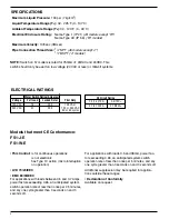
Maximum Liquid Pressure:

100 psi (7 kg/cm

2

)

Liquid Temperature  Range  (T

L

):

32 - 225˚F (0 - 107˚C)

Ambient Temperature  Range  (T

S

):

32 - 120˚F (0 - 49˚C)

Electrical Enclosure Rating:

Nema Type 1 (IP 21) 

(All models except “W”)

Nema Type 4X (IP 56) 

(“W” models)

Maximum Velocity:

10ft/sec (3M/sec)

Pipe Connection Thread Size:

1

/

2

” NPT 

(All models except “J”)

1

/

2

” BSPT 

(“J” models)

Models that meet CE Conformance:

FS1-J-E

FS1-W-E

• This Control:

is for continuous operations
is not electronic
has Type 1C action (micro interruption
on operation)

• LVD 73/23/EEC

• EMC 89/33/EEC

For applications with loads between 0.5 and 3.7 Amps,
power factors exceeding 0.65, an anticipated system
switch operation rate of less than once per 2.5 minutes,
and any one cycle greater than 3 seconds on and 3
seconds off.

For applications with loads 0.5 and 38mA, power fac-
tors exceeding 0.65, an anticipated system switch
operation rate of less than once per 5 minutes, and any
one cycle greater than 3 seconds on and 3 seconds off.

Additional suppression may be required for applica-
tions outside these ranges.

• Declaration of Conformity

Available on request.

SPECIFICATIONS

NOTE:

Switch on ‘G’ models is rated for 750mA @ 24VAC and 24VDC. This

switch should only be used on low voltage (24 VAC or less) or millivolt systems.

Motor Switch Rating (Amperes)

Voltage

Full Load

Locked Rotor

Pilot Duty

120 VAC

7.4

44.4

125 VA at

240 VAC

3.7

22.2

120 or 240 VAC

50 or 60 cycles

ELECTRICAL RATINGS

CE Circuit Rating

7.4 (7.4)/120~

0.3/120=

3.7 (3.7)/240~

0.15/240=

Summary of Contents for McDonnell & Miller FS1 Series

Page 1: ...To prevent an electrical fire or equipment damage electrical wiring insulation must have a rating of 167 F 75 C if the liquid s temperature exceeds 180 F 82 C To prevent electrocution when the electr...

Page 2: ...tch operation rate of less than once per 2 5 minutes and any one cycle greater than 3 seconds on and 3 seconds off For applications with loads 0 5 and 38mA power fac tors exceeding 0 65 an anticipated...

Page 3: ...n of the Flow Switch D 5 x D MINIMUM 1 2 PIPE 5 x D MINIMUM FLUID FLOW D PIPE DIAMETER The flow switch should be located in a horizontal section of pipe where there is a straight horizontal run of at...

Page 4: ...hex fitting of flow switch and one wrench on connecting piping Tighten to following torque values 31 ft lb 42 N m for 1 2 pipe Repeat to connect pipe to opposite side of flow switch a Apply pipe seali...

Page 5: ...trical Installation To prevent electrical shock turn off the electrical power before making electrical connections To prevent an electrical fire or equipment damage electrical wiring insulation must h...

Page 6: ...itch will be used to actuate a signal alarm or other device when no flow occurs connect the wire from that device to the N C contact Connect the Hot power supply wire to C terminal Flow Opens Circuit...

Page 7: ...quired flow switch may need to be adjusted OFF ON SECTION 4 Testing STEP 5 Adjustment 1 2 Pipe Connection Adjusting Screw Adjustment is necessary only if required flow no flow setpoints are above fact...

Page 8: ......

Reviews: