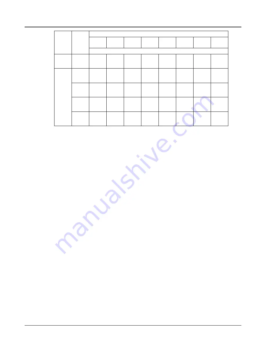
Material
Dimen-
sion
Pump Size
8x10-22 12x14-1
8
14x16-1
8
16x18-1
8
10x12-2
2
14x16-2
2
16x18-2
2H
18x20-2
2
Dimensions below in inches
D
.021
.025
.023
.029
.023
.029
.023
.029
.023
.029
.023
.029
.023
.029
.023
.029
Steel
A
8.989
8.987
10.753
10.751
12.236
12.233
13.982
13.979
10.238
10.236
12.982
12.979
14.234
14.231
15.355
15.352
B
.020
.024
.022
.026
.023
.029
.023
.029
.022
.026
.023
.029
.023
.029
.023
.029
C
9.854
9.852
12.477
12.474
13.102
13.099
14.852
14.849
11.102
11.100
14.477
14.474
15.602
15.599
16.477
16.474
D
.021
.02
.023
.029
.023
.029
.023
.029
.023
.029
.023
.029
.023
.029
.023
.029
4.
Gasket:
Inspect flange gasket. If torn or otherwise damaged, cut a new gasket of 1/64". Use the
upper half casing as a template. Strike the sheet with a ball peen hammer. This will cut the gas-
ket against the edge of the casing. The gasket must cover the entire surface of the flange, espe-
cially around the wearing ring locks, or internal leakage from high to ow pressure zones in the
pup will occur.
5.
Shaft:
Check shaft for runout to see that it is not bent, Straighten if required. Bearing sets must
be in perfect condition. Replace if necessary. Check always for burrs or foreign matter.
6.
Impeller:
Check impeller and replace if there is:
1.
Excessive erosion, especially on the inlet vanes.
2.
Excessive wear on wearing surfaces. If the impeller diameter has to be cut, it should be
dynamically balanced. Imbalance can be corrected by grinding on the outside of the
shrouds near the periphery.
7.
Shaft sleeve:
The sleeve surface in the stuffing box area must be smooth and free of grooves. If
grooved, replace. O-ring groove in end of sleeve must be in good condition.
The original diametric clearance between the shaft sleeve and the stuffing box bushing
is .030-.034". If this clearance has increased to more than .050-.060" the sleeve, and the stuffing
box should be replaced.
8.
Bearings:
Replace ball bearings if worn, loose, rough, or noisy when rotated. Refer to
.
9.
General:
All parts should be clean before assembly. This is especially important at O-ring
grooves, threads and bearing areas.
6.6 Reassembly
1.
Determine the correct positioning of impeller on shaft. Facing the coupling end of shaft, deter-
mine proper rotation of unit (clockwise or counter-clockwise).
proper relationship between rotation and impeller vane curvature for counterclockwise rotation.
2.
Slide impeller on shaft with key in place. Drive or press shaft into impeller. Do not damage end of
shaft. Line up impeller hub with scribe mark made on shaft during disassembly.
3.
Place O-rings in grooves in end of shaft sleeves. Slide sleeves on shaft.
6.6 Reassembly
42
Model 3415 Installation, Operation, and Maintenance Manual


