


www.ittcontrols.com
18
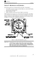
Section 3
Model 581A Differential Pressure Switch
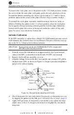
4. Bend the zero drive arm stop against the drive arm.
5. Verify calibration as applicable.
Switch Calibration
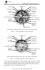
Before performing a complete calibration of the switch, perform a calibration
check (See
Calibration Check, page 12
). If the instrument is out of calibration,
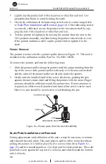
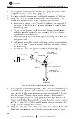
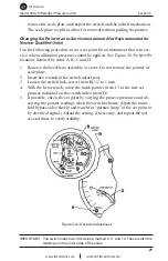
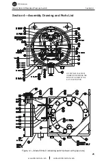
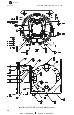
remove the bezel/lens and scale plate and inspect the switch mechanism (Fig-
ure 3.6) to verify the following:
• The roller rotates without wobble or binding.
• The cam does not touch the roller side shields.
• The actuator arm moves freely on its pivot.
• All switch mounting screws are tight.
• Linkages are straight and do not bind at the pivots.
Correct any problems that are observed. If no problems are observed, proceed
with a complete calibration.
SWITCH
ACTUATOR ARM
STOP
SCREW
PLUNGER
SCREW
CAM ROLLER
CAM
Figure 3.6—Switch mechanism
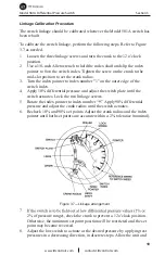
Calibration Setup
1. Connect an output device (lamp or buzzer) to the switch output leads.
2. Connect a test voltage to the switch input terminals on the terminal strip.
(A low voltage is recommended for safety.)
3. Unlock the switch plate and move the plate until the roller is positioned
at the top of the cam.
4. Advance the plunger screw until the switch actuates, then advance the
5. Exercise the switch roller across the top of the cam to verify steady
operation. Advance the stop screw to touch the switch, then back out the