ITRON IPC-E200N Quick Start Manual Download Page 9


of the plastic expansion bolts according to the diagram. Take three expansion bolts from 
the accessories bag and then insert them to the holes you just dug and then fix firmly. If 
you need to dig a hole to pull through the cable on top of installation surface, you need to 
dig a cable exit hole on the installation surface according to the installation positioning 
diagram. If you need to pull through the cable on the side, you need to dig through the U-
shape exit hole on the side of chassis.  
 

Step 3 

Adjust the device chassis and pull the cable through the exit hole. Make “TOP” direction 
of the device identical with installation diagram. Make fixture hole on chassis face the 
three plastic expansion bolts (in Step 1). Take 3 ST3.0 self-tapping screw out from the 
accessories bag and fix them on the three plastic expansion bolts to secure the chassis 
on installation surface. 
 

Step 4 

Line up the dome camera protection enclosure and follow step 1 reversely to put it back. 
Use the inner hex wrench from the accessories bag to fasten the 3 hex screws. For 
Micro-SD card installation, please refer to Chapter 2.3. 
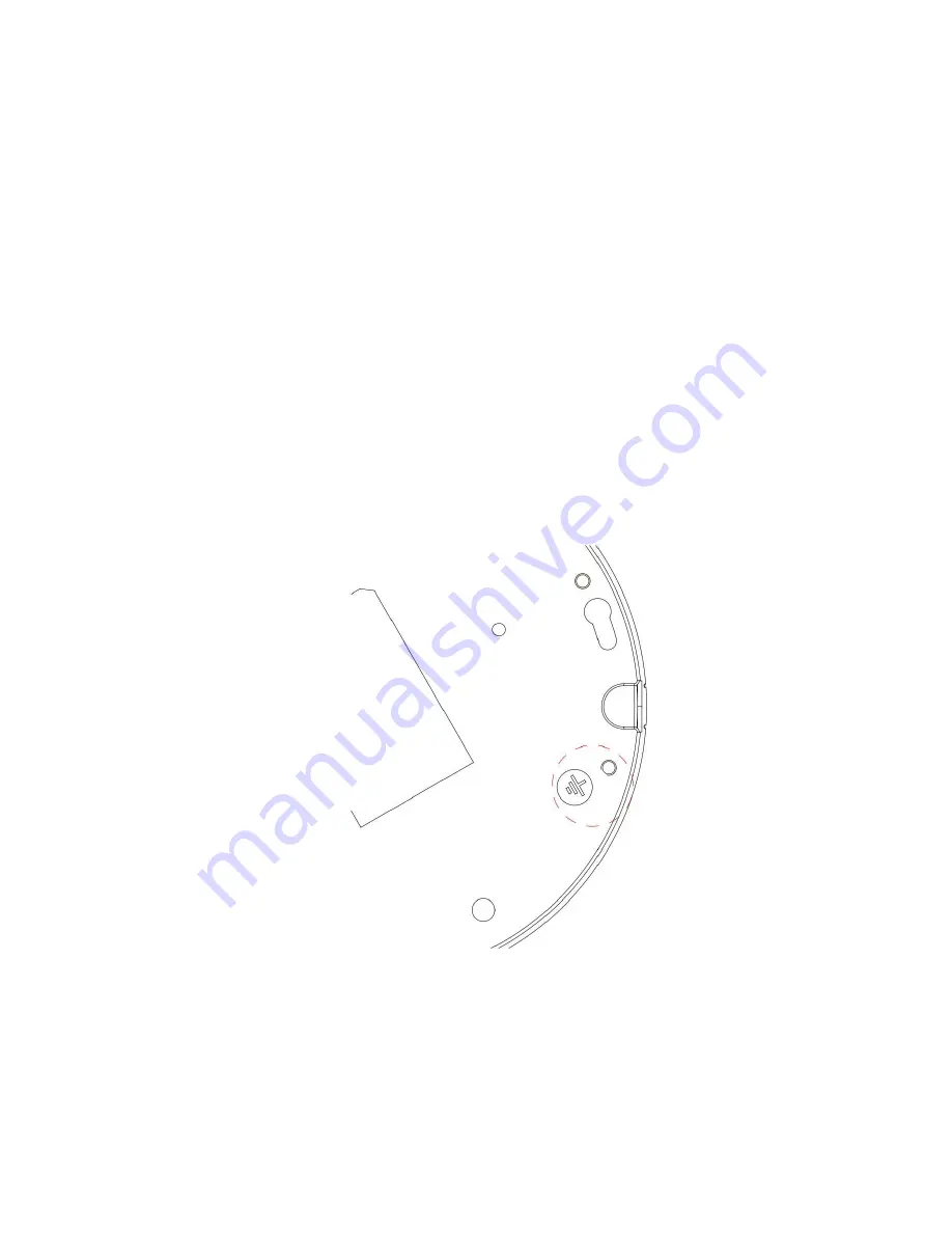
See Figure 2- 2 for grounding hole (GND). 


Figure 2- 2 


Note: If connect the GND to ground lead, may improve device reliability. The GND 
locates next to exit hole on chassis and the GND screw is M3. 

2.3


Micro SD Card Installation 

Warning! 

Summary of Contents for IPC-E200N

Page 1: ...i HD Panorama Network Camera Quick Start Guide Version 1 0 0...

Page 2: ...at the same time it may result in device damage We assume no liability or responsibility for all the fires or electrical shock caused by improper handling or installation We are not liable for any pr...

Page 3: ...le before you begin daily maintenance work Do not touch the CCD CMOS optic component You can use the blower to clean the dust on the lens surface Always use the dry soft cloth to clean the device If t...

Page 4: ...4 2 2 Device Installation Steps 4 2 3 Micro SD Card Installation 5 2 4 Manual Zoom Lens Focus Operation 6 3 Quick Configuration Tool 7 3 1 Overview 7 3 2 Operation 7 4 Web Operation 10 4 1 Network Co...

Page 5: ...lowing sheet for corresponding information 1 2Dimensions You can refer to the following figures for dimension information The Unit is mm See Figure 1 2 Figure 1 3 and Figure 1 4 Figure 1 2 No Port Por...

Page 6: ...2 Figure 1 3 Figure 1 4 1 3Bidirectional Talk...

Page 7: ...then click the Talk button to enable the bidirectional talk function You can see the button becomes orange after you enabled the bidirectional talk function Click Talk button again to stop the bidirec...

Page 8: ...he bracket and the camera 2 1General Installation Please refer to Figure 2 1 for device installation information You can see there are installation screws in the accessories bag for you to install the...

Page 9: ...e Make TOP direction of the device identical with installation diagram Make fixture hole on chassis face the three plastic expansion bolts in Step 1 Take 3 ST3 0 self tapping screw out from the access...

Page 10: ...ty Please put the enclosure back and fasten the screws tightly to prevent dust Step 1 Please refer to Step 1 in chapter 2 2 to open the device protection enclosure Step 2 Please find the SD mark insid...

Page 11: ...ure 3 1 Select one IP address and then right click mouse you can see an interface is shown as in Figure 3 2 Note You can set the IP address subnet mask and gateway for the network camera and PC Please...

Page 12: ...P address and then double click it to open the login interface Or you can select an IP address and then click the Login button to go to the login interface See Figure 3 4 In Figure 3 4 you can view de...

Page 13: ...uration tool main interface is shown as below See Figure 3 5 Figure 3 5 For detailed information and operation instruction of the quick configuration tool please refer to the Quick Configuration Tool...

Page 14: ...work camera default IP address is 192 168 1 108 Subnet mask is 255 255 255 0 Gateway is 192 168 1 1 Use order ping network camera address to check connection is OK or not 4 2Login and Main Interface O...

Page 15: ...click OK button and system will automatically install the control When system is upgrading it will overwrite the previous Web too If you can t download the ActiveX file please check whether you have i...

Page 16: ...ew installation mode and display mode at the right Please set installation mode according to actual installation condition 4 3 1 Installation Mode There are three modes wall mount in ceiling and groun...

Page 17: ...rama You can select video and then implement corresponding operation Where you can 1 Adjust camera direction via arrow keys Click OK to restore default position 2 Step length is mainly used for speed...

Page 18: ...upgrade the device via network When network upgrade operation failed you can use port 3800 to continue upgrading Recommended Micro SD card brand Kingston 4GB Kingston 16GB Kingston 32GB Transcend 16G...

Page 19: ...toxic or hazardous substance or elements contained in products will not leak or mutate so that the use of these substances or elements will not result in any severe environmental pollution any bodily...

Reviews: