16 / 21
IU_26779_1_ENG_MANUAL_SEMSC11
6.
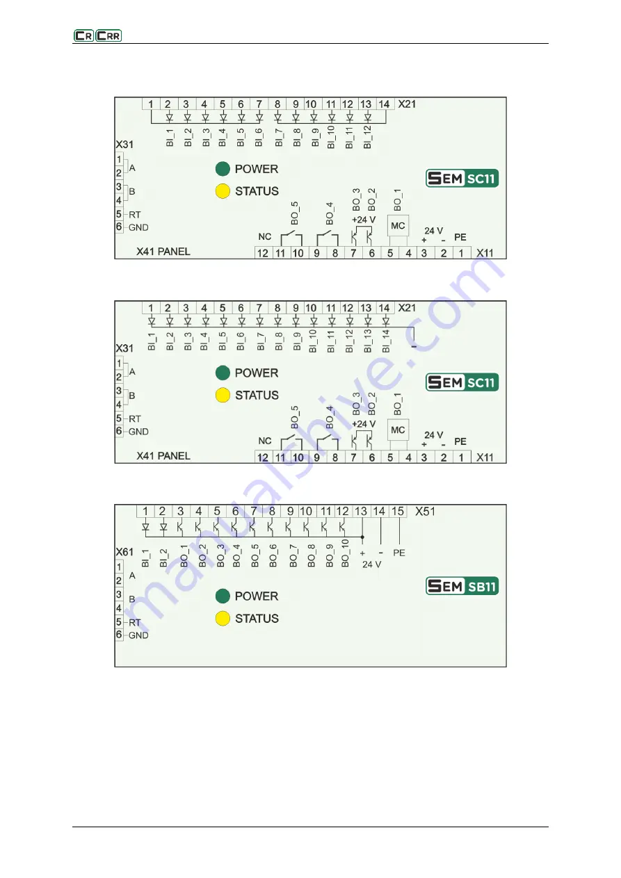
Wiring diagrams
Fig. 6.1. SEM SC11 device’s wiring diagram (12 inputs)
Fig. 6.2. SEM SC11 device’s wiring diagram (14 inputs)
Fig. 6.3. SEM SB11 device’s wiring diagram
Page 1: ...Current transducer User manual and technical documentation Document version 1 Update 05 05 2017...
Page 2: ...of protected object and result in threat to life and health Reliable and defect free operation of the device needs appropriate transportation handling storage installation and commissioning as well a...
Page 3: ...1 11 3 3 2 SEM Cxx 12 3 3 3 SEM Bxx binary inputs and outputs 13 4 Operating the device 14 5 Disturbance recorder 15 6 Wiring diagrams 16 7 Remarks of manufacturer 17 Maintenance inspections repairs...
Page 4: ...symbol indicates the presence of hazardous energy circuits or electric shock hazards The warning symbol indicates the important information related to the threat to life and health The information sym...
Page 5: ...ent commutating cycle recorder with the time registration of 20s The logic of operation of Smart Control SEMSC11 is based on the ELF application and can be freely edited by the user which makes it pos...
Page 6: ...BUS RTU protocol self monitoring functions STATUS led reprogramming functions through both transmission ports programmable logic including algorithms for monitoring and control of the commutating devi...
Page 7: ...systems For local control of the device PAN 1 or PAN 3 type detachable operator panels are used All modules are supplied with DC 24 V If there is a separate power supply in the switchgear for the comm...
Page 8: ...controlling remotely switching devices from the telemechanics 10 transistor DC 24 V binary outputs designed to transmit the operating status of switching devices to the telemechanics RS 485 link for...
Page 9: ...bol N ame Colour Description green Indicates that the correct supply voltage has been applied Steady light OPENED green Indicates an open connector Steady light CLOSED red Indicates a closed connector...
Page 10: ...nication interface depends on the parameters of the device to which it interacts The user interface consists of two signalling LEDs five buttons and a colour TFT display Table 3 4 Meaning of predefine...
Page 11: ...when it is applied only to In2 If voltages are present at both inputs or only at input In1 the power comes from the input In1 The status of operation on the power supply from In1 is confirmed by the...
Page 12: ...ature increments in distribution panels Control and monitoring of the status of switches in MV panels Current and voltage protections Automation monitoring and enforcing of the state of binary inputs...
Page 13: ...uts and outputs their state is represented with the LEDs located on the front panel The readout and analysis of input and output states is done using the main controller module SEM Cxx Fig 3 7 Module...
Page 14: ...s generate pulses of a certain duration to the output controlling the switching apparatus Control mode REMOTE telemechanics control Action of buttons is overridden The switch control takes into accoun...
Page 15: ...Fig 5 1 Recorded waveform of the switch control operation The recorder control is done using the function block placed on the logic diagram If the recorder is active the appearance of a rising edge on...
Page 16: ...16 21 IU_26779_1_ENG_MANUAL_SEMSC11 6 Wiring diagrams Fig 6 1 SEM SC11 device s wiring diagram 12 inputs Fig 6 2 SEM SC11 device s wiring diagram 14 inputs Fig 6 3 SEM SB11 device s wiring diagram...
Page 17: ...hould not exceed 80 Place of installation 7 3 SEM SC11 and SEM SB11 are designed for setting up on 35 mm DIN rail Mounting of PANx and accessories are described in separate documentation The total len...
Page 18: ...in the network following types of connections are used Type I intermediate position without RT resistor matching wave impedance of the line Type II extreme position with RT resistor matching wave impe...
Page 19: ...MSC11 19 21 Fig 8 2 Type II extreme position with RT resistor matching wave impedance of the line Fig 8 3 Connection between SEM SC11 and SEM SB11 modules Fig 8 4 Connection between SEM SC11 and PAN 1...
Page 20: ...rrent measurement 14 Extension module none 0 SEM SB 11 1 Panel none 0 PAN 1 1 PAN 3 3 Accessory SPS 24 1 AK1 USB 2xRS485 converter Telemechanics controller SEM Cxx Order example SC A12 B0 P0 12 inputs...
Page 21: ...6779_1_ENG_MANUAL_SEMSC11 21 21 10 Contact Tele and Radio Research Institute ICT and Electronics Centre 03 450 Warsaw ul Ratuszowa 11 tel 48 22 590 73 91 e mail energetyka itr org pl www energetyka or...