ITech IT-E500 Series User Manual Download Page 11


IT-E500 User Manual


Copyright© Itech Electronics Co., Ltd. 
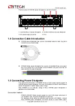


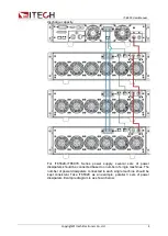
Connect the power supply and power dissipater based on the above 
schematic diagram. 
1.  Connect the external load’s connection terminal of IT6500C Series 

power supply to the load input interface of IT-E500 Series power 
dissipater. Connections of other power dissipaters are as shown  in 
blue lines in the figure. 

2.  Connect the control bus, as the green lines shown. Directly insert the 

network cables. 

3.  AC  input connection of power dissipater.  The power dissipater is 

configured with a piece of three-core power line. The user needs to 
connect the power line to the AC output terminal at the IT6500C rear 
panel, as the red lines shown above. Note that the L, N and earth 
terminals should be corresponding. 
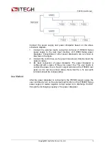
Use Method 

After the power dissipater is connected to the IT6500C power supply, the 
user can directly turn on the external load function on the IT6500C Series 
power supply to realize negative current output or to discharge the DUT 
through the discharging capacity of the power dissipater. 

Summary of Contents for IT-E500 Series

Page 1: ...Power Dissipater IT E500 Series User Manual Model IT E502 IT E503 IT E504 IT E505 IT E506 IT E507 Version No V2 2...

Page 2: ...s in this document that conflict with these terms the warranty terms in the separate agreement shall prevail Technology Licenses The hardware and or software described herein are furnished under a lic...

Page 3: ...as all the freights duties and other taxes shall be on the account of customer Limitation of Warranty This Warranty will be rendered invalid if the product is Damaged resulting from customer wired cir...

Page 4: ...al use The expected useful life of the product is 10 years The product can be used safely during the 10 year Environment Friendly Use Period EFUP Upon expiration of the EFUP the product must be immedi...

Page 5: ...4 2 2008 EN 61000 4 2 2009 IEC 61000 4 3 2006 A1 2007 A2 2010 EN 61000 4 3 2006 A1 2008 A2 2010 IEC 61000 4 4 2004 A1 2010 EN 61000 4 4 2004 A1 2010 IEC 61000 4 5 2005 EN 61000 4 5 2006 IEC 61000 4 6...

Page 6: ...ARRANTY 1 SAFETY SYMBOLS 1 REGULATORY MARKINGS 2 WASTE ELECTRICAL AND ELECTRONIC EQUIMENT WEEE DIRECTIVE 2 COMPLIANCE INFORMATION 3 CHAPTER1 ABOUT IT E500 1 1 1 GENERAL 1 1 2 DIMENSIONS 1 1 3 FRONT PA...

Page 7: ...ize external load function The single module of IT6500C power supply can parallel maximum 3 sets of power dissipaters with same voltage specifications to extend the power range of external load With t...

Page 8: ...ser Manual Copyright Itech Electronics Co Ltd 2 1 3 Front Panel and Rear Panel Introduction The front panel of IT E500 power dissipater is as shown below Ventilation hole Handle Instrument legs Power...

Page 9: ...he IT6500C rear panel and the AC input terminal of power dissipater 1 5 Connecting Power Dissipater The external load function of IT6500C Series power supply needs support of IT E500 Series power diss...

Page 10: ...eries power supply several sets of power dissipaters should be connected based on number of single machines The number of power dissipaters connected to each single machine should be kept consistent T...

Page 11: ...ectly insert the network cables 3 AC input connection of power dissipater The power dissipater is configured with a piece of three core power line The user needs to connect the power line to the AC ou...

Page 12: ...A 120A Power 0W 3000W Interface System Bus Dimention WxHxD 483 mm x 133mm x 504 3mm Weight 25Kg AC Input Voltage 100 240V AC Frequency 47 63 Hz Working current 2 5A 110V 1 25A 220V IT E503 Specificati...

Page 13: ...equency 47 63 Hz Working current 2 5A 110V 1 25A 220V IT E505 Specification Parameters IT E505 DC Section Input Rating Voltage 0 1 500V Current 0 1 20A Power 0 3000W Other Interface System Bus Dimenti...

Page 14: ...63 Hz Working current 2 5A 110V 1 25A 220V IT E506 Specification Parameters IT E507 DC Section Input Rating Voltage 0 1 1000V Current 0 1 10A Power 0 3000W Other Interface System Bus Dimention WxHxD...

Page 15: ...as follow 1 Please refer to the CD ROM of related user s manual in package 2 Click www itechate com or scan the right two dimension code to visit the ITECH website 3 Send E mail to fae itech sh or dia...

Reviews: