background image


Operating manual: PHOTOMETER FM-4           13

3. 4.  Data Logging 


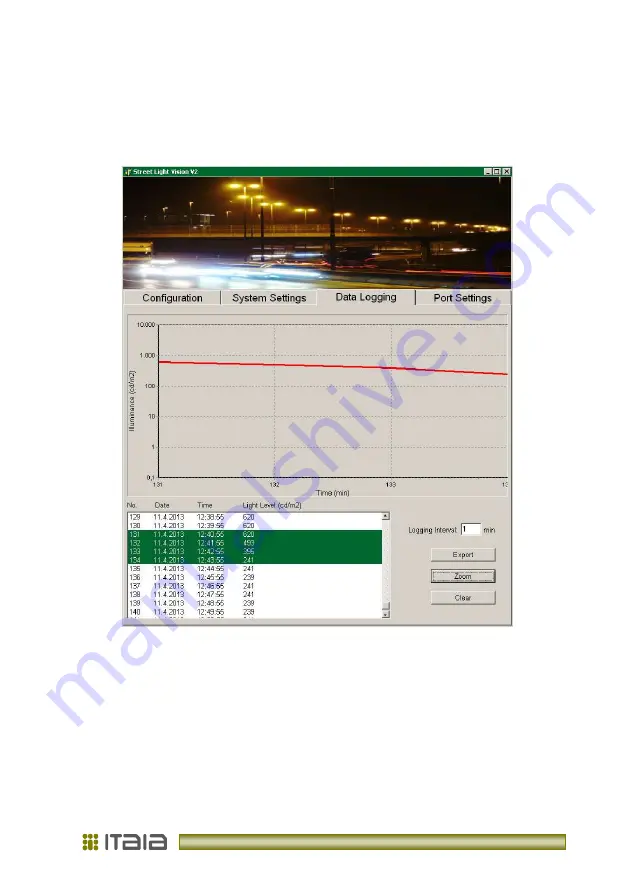
Light level monitoring and data logging parameters are set on Data Logging tab  
(Picture 5).  


Picture 5: Data Logging –zoomed view 


Light  Level  Read  field  in the  Configuration  tab must  be set  to Auto to  activate the  data 
logging. Table, graph and data file are updated every time when Light Level data is read 
from  photometer.  Logging  interval  is  time  in  minutes  between  two  readings.  The 
numerical data between 1 and 60 minutes can be selected. If number 0 is selected, than 
logging interval is 1 second. 
 
To save logged data click Export button and save *.txt file to your computer. The dialog 
window appears to select the name and file location. 
 

Summary of Contents for Photometer FM-4

Page 1: ...Operating manual Photometer FM 4 Litostrojska cesta 44 d SI 1000 Ljubljana T 386 1 514 18 00 F 386 1 514 18 04 info itaia si www itaia si ELECTRONICS RESEARCH DEVELOPMENT...

Page 2: ......

Page 3: ...ation Port 6 2 4 2 Use of 230 V AC Contactor Outputs 7 2 5 CALIBRATION 7 3 PC SOFTWARE STREET LIGHT VISION 8 3 1 WRITING DATA TO THE PHOTOMETER 9 3 2 READING DATA FROM THE PHOTOMETER 10 3 3 SETTING UP...

Page 4: ...F DEVICE MUST BE CARIED OUT BY QUALIFIED PERSONNEL WHEN CONNECTING DISCONNECT ELECTRICAL POWER FIRST DO NOT BLOCK ACCESS TO ELECTRICAL PARTS USED FOR EMERGENCY STOP CLEANING AND MAINTENANCE ALL METAL...

Page 5: ...s disconnected during the time of mounting and connecting Check the voltage presence with an instrument Check grounding connection Provide protection against touching the parts under voltage Qualified...

Page 6: ...F 386 1 514 18 04 info itaia si www itaia si Declaration of Conformity The device complies with relevant European directives CE declaration of conformity Electromagnetic compatibility ULRS no 132 2006...

Page 7: ...foldings or joints When it is used to measure in tunnel light conditions it should be mounted at the height of app 4 5 metres and pointed to the spot one reach in 3 seconds at maximum allowed speed I...

Page 8: ...6 contactor out D 230 V AC contactor out D 7 out out C 230 V AC contactor out C 8 out B 230 V AC contactor out B 9 out A 230 V AC contactor out A 10 PC GND 0 V DC programming control 11 RS 232 RX 12...

Page 9: ...r the user 2 4 1 Serial Communication Port The photometer s selectable communication port can be configured for RS 232 or RS 485 Set jumpers J1 J3 to select the protocol Connection distance can be up...

Page 10: ...LEDs and contactor outputs Green LEDs indicate estimated switch level combination no averaging delay due to current light condition Red LEDs indicate current status of 230 V AC outputs averaging affec...

Page 11: ...tor photometer s working parameters Install the software to any folder on the computer running MS Windows 2000 or higher The program is executed by clicking SLV icon Graphical user interface of the pr...

Page 12: ...th the combination used when the highest level specified is exceeded see Picture 3 Table 2 Averaging interval is the moving average of light level calculating time in minutes before contactor outputs...

Page 13: ...ice matching ID After reading data is refreshed in all fields Light Level Read Manual setting reads light level and any other device s parameter by clicking Read button Use Auto setting to read light...

Page 14: ...For RS 232 485 settings on the photometer see 2 4 1 Serial communication Port in this manual Picture 4 Photometer System Settings StreetLightVision software selects COM1 as the default If port is occu...

Page 15: ...edure when there is another device with the same ID on the bus only Write new ID into the field and click New ID button The numerical data within 0 255 can be selected Make sure to write down new ID I...

Page 16: ...uto to activate the data logging Table graph and data file are updated every time when Light Level data is read from photometer Logging interval is time in minutes between two readings The numerical d...

Page 17: ...nths interval clean the housing 1 year interval and recalibrate 3 year interval Note The device requires regular checking and maintenance Keep your maintenance and service log up to date Shorten check...

Page 18: ...rial port Note No communication note appears by unsuccessful communication with photometer check ID number of the device check power supply and data connection to the photometer Note Communication err...

Page 19: ...A 5x20 mm Casing IP67 Aluminium Stainless steel ABS Size W x H x D 395 x 135 230 x 145 mm Weight 2 8 kg Fixture wall X Y adjustable fixture pole optional Communication port RS 232 485 9600 bps Contact...

Page 20: ...conditions Production year is visible on the back side sticker Deteriorated or ruined device dispose to the place for industry electronic components disposal according to local regulation Components p...

Page 21: ...Safety requirements for electrical equipment for measurement control and laboratory use Part1 General requirements SIST EN 61000 3 2 2006 EMC Part 3 2 Limits for harmonic current emissions equipment...

Page 22: ...ist in case of improper use or use in discordance to this manual in case of mechanical damage in case of consequential damage due to failure or damage of other devices in case of natural or environmen...

Page 23: ...V 1 2 rev 12 2012...

Page 24: ...Litostrojska cesta 44 d SI 1000 Ljubljana T 386 1 514 18 00 F 386 1 514 18 04 info itaia si www itaia si...

Reviews:

Related manuals for Photometer FM-4