background image

Operation

Device overview

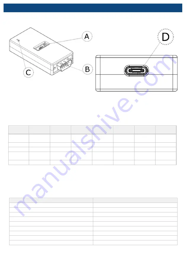
Device description

A

 – DAP connector

Pinout valid on the DAP connector side:

Signal

Description

Signal

Direction

Signal

Pin

Pin

Signal

Signal

Direction

Signal

Description

Reference

voltage

O

Vref 

1

2

TXD

I

Transmitter

Ground

GND

3

4

NC

Not Connected

Ground

GND

5

6

RXD

O

Receiver

Not

Connected

NC

7

8

NC

Not Connected

Ground

GND

9

10

NC

Not Connected

DAP connector pinout

Signal Direction is described from the BlueBox perspective.

– DB9 connector

Pinout valid on the DB9 connector side:

Pin

Signal

1

Not Connected

2

CAN_L

3

CAN GND

4

NC

5

SHIELD

6

NC

7

CAN_H

8

NC

9

NC

DB9 connector pinout

C

 – The LED indicator provides the status of the hardware as follows:

Summary of Contents for DAP over CAN

Page 1: ...DAP over CAN User Manual V1 3 ...

Page 2: ...d by iSYSTEM AG and all rights are reserved Duplication of these documents is allowed for personal use In all other cases written consent from iSYSTEM is required iSYSTEM AG All rights reserved All trademarks are property of their respective owners www isystem com ...

Page 3: ...Contents DAP over CAN Package content 5 Operation 6 winIDEA Configuration 8 Accessories 9 User Notes 10 ...

Page 4: ...frequency Its small and compact hardware size allows for connecting to a target microcontroller in a confined space as far as 5m away Infineon AGBT Active Probe Enables debugging tracing and testing of Infineon s AURIX microcontroller family It supports the DAP and Aurora GigaBit Trace AGBT interface operating at their maximum frequency Its small and compact hardware size allows for connecting to ...

Page 5: ...Package content The DAP over CAN Physical Layer Converter is delivered with the following components DAP over CAN Physical Layer Converter USB C cable User Manual Ordering code IEA DXCPL ...

Page 6: ...er Ground GND 3 4 NC Not Connected Ground GND 5 6 RXD O Receiver Not Connected NC 7 8 NC Not Connected Ground GND 9 10 NC Not Connected DAP connector pinout Signal Direction is described from the BlueBox perspective B DB9 connector Pinout valid on the DB9 connector side Pin Signal 1 Not Connected 2 CAN_L 3 CAN GND 4 NC 5 SHIELD 6 NC 7 CAN_H 8 NC 9 NC DB9 connector pinout C The LED indicator provid...

Page 7: ...he Converter Use provided USB C cable to power the converter e g from a PC CAN 120 Ohm terminating resistor is not implemented on the DAP over CAN Physical Layer Converter iSYSTEM provides cable solutions on request with build in terminating resistor which can be easily switched on or off ...

Page 8: ...over CAN Physical Layer Converter in winIDEA 1 Open Hardware menu CPU Options 2 Navigate to the SoC page 3 Select DXCPL from the Debug channel Mode drop down 4 Confirm and establish the debug connection Refer to isystem com connect for more information on how to connect and configure the hardware ...

Page 9: ...FNET 500 5 0m FNet Cable Active Probe BB FNETMICRO 100 1 0m FNet Micro Cable Active Probe Please refer to the iC5700 BlueBox for all current iC5700 Accessories The functionality of the DAP over CAN Physical Layer Converter can be extended through the use of various accessories Ordering Code Description IC57040 CAN DB9 1m CAN cable DB9 plug IC57040 CAN PIN CAN cable pin wires IC57040 CAN JACK CAN c...

Page 10: ...User Notes This page is intentionally left blank ...

Page 11: ...This page is intentionally left blank ...

Page 12: ... information provided in this document at the time of publishing Whilst iSYSTEM reserves the right to make changes to its products and or the specifications detailed herein it does not make any representations or commitments to update this document iSYSTEM All rights reserved ...

Reviews: