SPEAKER POWER
:
The HDDS system distributes low voltage Alternating Current over the Cat5 cable plus
high level balanced audio and is capable of greater than 30 watts continuous power per
speaker SM650. Each of the three outputs A, B and C are capable of delivering up to 7
amps of output current. With a typical power per speaker of 10 watts each speaker will
consume on the order of 400mA, which means that 12 speakers would require 4,800mA
of current. Installed systems that require more output power per speaker simply
require that the number of speakers per output A, B and C be reduced so as not to
exceed the maximum of 7 amps available. The current consumption at full power (30
watt continuous) will require over 1 Amp of power per speaker. In order to allow the
full 30 watts of power where higher output levels are desirable the number of speakers
per A, B and C outputs on each zone needs to be limiting the maximum number 5.
Reducing to 20 watts of power per speaker, a maximum of 8 speakers per output can
be connected to each A, B and C zone output. With longer runs of cable exceeding 150
feet the cable voltage drop will start to become a design factor. The Cat5 cable will
start to limit the total power capability once you exceed 75 feet of cable. Where
maximum power output is critical a more precise calculation can be done by following
the speaker consumption guide.
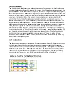
Cat5 Connections
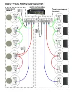
The figure below shows the connections for each output A, B and C of each zone output
on the Master Control Module and also connections between each SM650 speaker.
Connections are done via standard Cat5 cables where pins 1 through 8 are connected
common to the same pins 1 through 8 at each end. As shown below two wires in the
Cable are use for balanced audio and 6 wires are used for power with two providing
ground and two for each of two 22VAC power signals fed down the cable.


