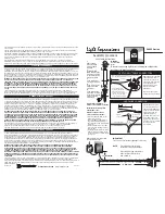
WIRING DIAGRAM
26
19
21
1
2
3
4
5
13
19
10
32
31
30
29
28
24
23
22
14
11
15
16
12
25
32
26
27
20
18
8
9
17
7
6
33
Figure 1
Figure 2
TEST
CHARGE
AC ON
WHITE - Neutral / Common
GREEN - Ground
BATTERY
NEG
-
POS
+
BATTERY -
LAMP +
LAMP
-
CHARGER PC BOARD
ASSEMBLY
LAMPS
STANDARD TRIPLE INPUT VERSION
RED - 347V Line / Hot
FUSE
CHARGER BOARD
BLACK - 120V Line / Hot
ORANGE - 277V Line / Hot
PARTS LIST
1. Torx tamper proof screw 8-32 x 1
2. “O” ring 1/16 wide x 5/32 ID x 9/32 OD
3. Stencil
4. Red fiber
5. Frame gasket
6. LED holder
7. LED light
8. Weld nuts
9. LED board
10. Not supplied
11. Base
12. Torx tamper proof screw 8-32-1/2”
13. 8-32 x 1/2 inch oval head screw, Phillips
14. Test switch
15. MR16 holder
16. MR16 lamps
17. Cover
18. Socket
19. Capscrews
20. MAX combo lens
21. Battery
22. Switch cover
23. MAX frame
24. Inside mounting plate
25. Circuit board
26. Back plate gasket
27. MAX back plate
28. Gasket for canopy to frame sealing
29. Canopy for exit
30. Canopy gasket
31. Mounting base for canopy
32. Bushing
33. Lens
Isolite 31 Waterloo Avenue, Berwyn, PA, 19312 Phone: (610) 647-8200 Fax: (610) 296-8952


