


3.
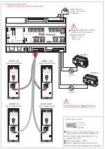
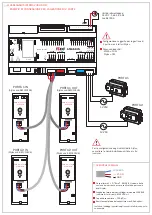
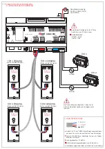
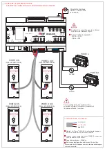
V364 RFID SYSTEM WIRING:
2 DOORS CONTROLLER CONNECTION EXAMPLE
ATLAS DIN
Console
Battery
ON
Res
et
W
ak
e u
p
Switc
h O
FF
ON
GN
D
+5
V
+V
OU
T
O
UT
1
IN
1
GN
D
A
nalog I
N
GN
D
+V
P
owe
r
GN
D
SE
R.
A
SE
R.
B
COM
NO
NO
COM
R
US
B
CH0
Relay
1
Relay
2
IN
2
IN
5
IN
3
IN
4
GN
D
+5
V
R
1
R
3
LE
D
2
LE
D
1
R
2
R
5
R
4
+V
P
owe
r
GN
D
SE
R.
A
SE
R.
B
CH1
AUX
+V
P
owe
r
GN
D
SE
R.
A
SE
R.
B
CH2
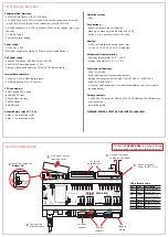
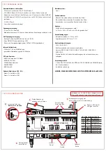
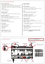
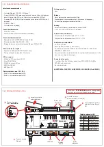
Power IN
12 VDC - 800 mA
24 VDC - 400 mA
MADE IN ITALY
Power supply unit:
24 VDC - 1,65 A (35 W)
Cod.5E3005
12 VAC
12 VAC
DOOR 1
Back side view
circuit board
DOOR 1 IN
(Stylos cod.5E1310126)
S1
DOOR 2
Total LOCKBUS channel cable length (sum of all
branches): MAX 100mt.
Conductor capacitance < 100pF/m.
Conductors electrical resistance max 90 ohm/Km.
Cable 3 x 0,75mm - AWG 18 (
the calculation of the
cables section must be verified by qualified staff).
WIRING SPECIFICATIONS
LOCKBUS
(+) V ALIM
( ) GND
DOOR 2 IN
(Stylos cod.5E1310126)
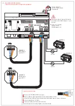
Back side view
circuit board
Back side view
circuit board
DOOR 1 OUT
(Stylos cod.5E1310126)
S1
DOOR 2 OUT
(Stylos cod.5E1310126)
Back side view
circuit board
Devices consumption:
- ATLAS = 10 W
- Stylos = 3W
2
Suggested configuration for 2 doors
controller: max 4 Stylos readers.
Wires colors reported in the wiring diagrams are just an example.
For the Stylos address configuration refer to the
Stylos Installation Guide
, available at:
iseo.com
.


