Positioning module UVE8112, IMD10 DcSetup
programme
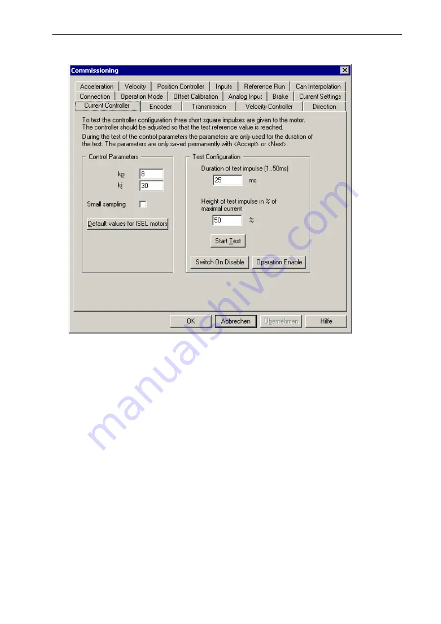
Current Controller dialogue box
The setting of the PI current controller is realised via the parameters
kp
(proportional amplification)
and
ki
(integral amplification). Based upon the default values, the controller settings can be
optimised. In order to facilitate the setting process, an internally generated rectangular signal (three
pulses) is applied on the controller’s input for the test. Here, the overall duration and the amplitude
im
of the test signal can be set. The path of the actual current is recorded internally and then queried
and displayed by the DcSetup programme (see Figure). For the setting of the controller, it has to be
made sure that the target value (dotted line) is achieved and maintained.
The selection of the “Short scan time” option causes a quicker clocking of the current controller. A
faster current control is very useful for the correction of errors such as e.g. in case of a toothed belt
forward feed.
Note: If the motor does not have to drive a large mechanical load and if the duration of the test
impulse is too long, it may be that the motor goes into saturation and that the current decreases.
49
Summary of Contents for IMD1
Page 1: ...DC servo positioning module with CanOpen interface UVE8112 IMD10 www isel com ...
Page 66: ...DcSetup programme Positioning module UVE8112 IMD10 66 ...
Page 113: ...Positioning module UVE8112 IMD10 Appendix 113 Appendix UVE8112 package dimensions ...
Page 114: ...Appendix Positioning module UVE8112 IMD10 114 IMD10 package dimensions ...


