background image

iBC 10 

– Hardware description 


3

  Connections 


3.1

  Connection for power supply  (X1/Power IN) 

 
Here the output of the DC-power supply unit is connected. This is decoupled via a 

diode from the outputs of the final stages. 


3.2

  Connection for final stages (X1/Power OUT) 

 
The final stages are affiliated to the above-mentioned diode decoupled voltage. Up 

to 5 final stages can be connected. However, the permissible total current  

     of 15 A must not be exceeded. Short-term peak loads are permitted. 
 

3.3

  Distributor (X2/A,B) 

 
These connectors are for internal use only.  The pin "A" and "B" are each bridged. 

Here, for example, fans can be clamped in parallel.  


3.4

  Fault-Output (X2/C,E) 


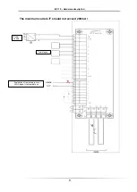
The terminals C and E are used for internal temperature monitoring. If the terminal 

C connected to +24 V, thus leading to the terminal E +24 V, as long as the 
temperature limit is not exceeded. Upon reaching the shutdown temperature of 75 
° C, the temperature monitoring interrupts a24 V -> 0V at terminal E. After 
cooling, the sensor switches itself back on -> +24 V at terminal E.  

The connection should be wired to use the internal monitor the temperature. 

Summary of Contents for IBC 10

Page 1: ...isel Germany AG D 36124 Eichenzell Bürgermeister Ebert Str 40 49 0 6659 981 700 49 0 6659 981 776 Stand 07 2014 IBC 10 User manual Hardware description ...

Page 2: ...oftware and hardware descriptions of each individual company are generally subject to protection of trademarks and patent law All rights reserved It is not permitted to reproduce or electronically process duplicate or spread any part of our prints in any way print copy etc without written permission of isel Germany AG Manufacturer isel Germany AG Bürgermeister Ebert Straße 40 D 36124 Eichenzell Te...

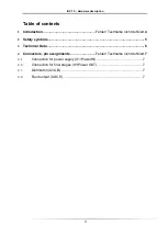
Page 3: ...extmarke nicht definiert 4 2 Safety symbols 5 3 Technical Data 6 4 Connectors pin assignments Fehler Textmarke nicht definiert 7 4 1 Connection for power supply X1 Power IN 7 4 2 Connection for final stages X1 Power OUT 7 4 3 Distributor X2 A B 7 4 4 Fault output X2 C E 7 ...

Page 4: ...ng defects and malfunctions of parts of the controller are avoided The module has an internal temperature monitoring A special floating output is suitable to evaluate the status of the external monitoring for example by a PLC or an isel residual interpret module In case of over temperature the output is open Connect the output X2 C E according to avoid over temperature of the brake chopper module ...

Page 5: ...zed personnel and in accordance with the requirements of the electrical industry as well as the accident prevention regulations Assembly and use of resources must be performed according to the standards of the Declaration of Conformity The rules and regulations as well as the limit values which were kept from the manufacturer do not protect in case of improper use of resources The device must not ...

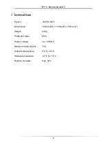
Page 6: ...al Data Part no 390194 4001 Dimensions 180mm W x 110mm H x 35mm D Weight 538 g Protection class IP20 Supply voltage 24 100VDC Maximum rated current 15A Ambient temperature 5 C to 40 C Storage temperature 25 C to 70 C Relative Humidity max 95 ...

Page 7: ... term peak loads are permitted 3 3 Distributor X2 A B These connectors are for internal use only The pin A and B are each bridged Here for example fans can be clamped in parallel 3 4 Fault Output X2 C E The terminals C and E are used for internal temperature monitoring If the terminal C connected to 24 V thus leading to the terminal E 24 V as long as the temperature limit is not exceeded Upon reac...

Page 8: ...iBC 10 Hardware description 8 The maximum curretn IF should not exceed 200mA Evaluation of temperature error HIGH signal temperature ok Final stages Power supply ...

Reviews: