


OPERATION
45
CAUTION: Make sure all PTO shields are
installed on Tractor and equipment. Before
cleaning or adjusting Tractor or PTO driven
machine, SHUT OFF ENGINE AND DISEN-
GAGE PTO.
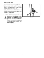
Mid PTO Shaft (M Type)
FIG. 5-21: Mid PTO, 1, is forward-facing shaft located at
underside of Tractor. This is installed to operate certain
mid or front-mounted implements. A 1" (25.4mm) fifteen
spline shaft is used.
Mid PTO cover must be installed when use of mid PTO is
not required.
(Mechanical Transmission)
2000 rpm @ 2500 engine rpm (TH4290)
2000 rpm @ 2500 engine rpm (TH4260)
(Hydrostatic Transmission)
2080 rpm @ 2600 engine rpm (TH4330)
2000 rpm @ 2500 engine rpm (TH4290)
2000 rpm @ 2500 engine rpm (TH4260)
CAUTION: Make sure all PTO shields are
installed on Tractor and equipment. Before
cleaning or adjusting Tractor or any PTO
driven machine, SHUT OFF ENGINE AND DIS-
ENGAGE PTO.
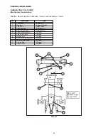
PTO Operating controls (Mechanical Transmission)
FIG. 5-22: These tractors have a dual clutch. To select
the rear PTO, push the clutch pedal completely down, to
disengage drive to PTO drive train. Allow time for drive
train to stop and then move lever (2) at the left of the seat
to the 540 rpm position.
To engage the PTO, slowly release the clutch pedal,
through the first stage, then increase engine speed to
obtain 540 PTO rpm. With the PTO running at 540 rpm,
and a correct transmission gear selected, release the
clutch pedal through the second stage to start forward
travel.
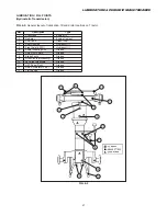
FIG. 5-23: To select the mid mounted PTO, use the same
procedure as outlined rear PTO, but use the mid PTO
control lever. With the clutch pedal fully depressed move
the lever (3) to
M
position to engage the PTO and to
N
position to disengage it.
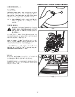
IMPORTANT: Before moving the rear and mid-PTO
selector levers, the clutch pedal must be
depressed to disengage power to the
drive.
NOTE: Determine the PTO engaging position on your
tractor by checking the label on it.
FIG. 5-21
FIG. 5-22 (Mechanical Transmission)
FIG. 5-23 (Mechanical Transmission)
Summary of Contents for TH4260
Page 72: ...TH4330 4290 4260 72 FIG 6 34 3 FIG 6 34 4 ...
Page 91: ...ISEKI TRACTOR 91 ...
Page 92: ...TH4330 4290 4260 92 ...
Page 93: ...WIRING DIAGRAM WIRING DIAGRAM WIRING DIAGRAM TH4260F ...
Page 94: ...WIRING DIAGRAM TH4260FH ...
Page 95: ...WIRING DIAGRAM TH4290F ...
Page 96: ...TH4330 4290 4260 WIRING DIAGRAM TH4290FH 4330FH ...


