10
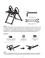
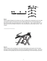
Step 3
Mount the Backrest Frame (2) to the Pivot Arms (11) by inserting the ends of the Pivot Arms (11) into
the brackets, located at each side of the Backrest Frame (2), align to the bolt holes on the Pivot Arms
(11) and brackets. Using four M8x20mm Hexagon Socket Head Cap Bolts (28), four Ø16xØ8.5x1.5
Flat Washers (19), and four M8 Nylon Nuts (Black) (21) to attach the Backrest Frame (2) onto the
Pivot Arms (11). Tighten bolts and nylon nuts with provided the Wrench and Allen Wrench.
Hardware:
․․․․․․․․․․․․․․․․․․․․․․․․․․․․․․․․․․․․․․․․․․․․․․․․․․․․
․․․․․․․․․․․․․․․․․․․․․․․․․․․․․․․․․․․․․․․․․․․․․․․․․․․․
․․․․․․․․․․․․․․․․․․․․․․․․․․․․․․․․․․․․․․․․․․․․․․․․․․․․
․․․․․․․․․․․․․․․․․․․․․․․․․․․․․․․․․․․․․․․․․․․․․․․․․․․․
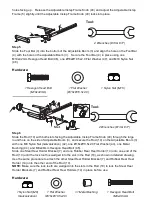
Step 4
Pull up on the Adjustable Instep Frame Knob (40), slide the Adjustable Instep Frame (5) completely
out of the Adjustable Boom (3) and then turn the Adjustable Instep Frame (5) with the adjustable
3
5
40
3
1
2
28
28
19
21
19
11
11
Tool:
1 Allen Wrench #6
1 Wrench (#13 & #17)
4 Flat Washers
(Ø16xØ8.5x1.5)
4 Nylon Nuts (M8)
(Black)
4 Hexagon Socket Head
Cap Bolts (M8x20mm)
Summary of Contents for 5501
Page 5: ...4 WARNING LABEL PLACEMENT ...

