background image

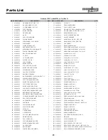
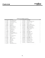
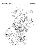
Parts List

REF# KEYS PART#

DESCRIPTION

QTY.

REF# KEYS PART#

DESCRIPTION

QTY.

1

423-00008

CROSS BAR 150T, 220T, 7.3T

1

54 402-00046

CLIP NUT

8

2

406-00055

BASE BUMPER, 38*33*15

2

55 406-00034

TRANSPORT WHEEL

2

3

406-00056

LONG BUMPER, 43*35*45

2

56 404-00004

POLY V-BELT, 190J8

1

4

423-00009

LEFT UPRIGHT

1

57 404-00003

WALK BELT, 20*56, IRONMAN LOGO

1

5

423-00010

RIGHT UPRIGHT

1

58 403-00002

WALK BOARD, 150/220/320T, 20*56

1

6

423-00011

DECK FRAME

1

59 406-00035

DECK BUMPER, 24*20

8

7

423-00012

BASE

1

60 410-00014

ALLEN WRENCH HANGER

1

8

419-00007

ELEVATION FRAME

1

61 406-00045

ADJUST SUPPORT

2

9

419-00008

MOTOR FRAME

1

62 409-00003

FRONT ROLLER, 150T,220T,320T

1

10

405-00002

SIDE BOARD - LATCH SIDE

1

63 409-00004

REAR ROLLER, 150T,220T,320T

1

11

405-00003

SIDE BOARD

1

64 410-00019

GAS SPRING

1

12

419-00010

LINKAGE  BRACKET

2

65 419-00012

REAR WHEEL SHAFT

4

13

419-00009

REED SWITCH PLATE

1

66 402-00051

SHOULDER ALLEN BOLT 1/4"-20*63.5

2

14

419-00011

SIDE MOTOR COVER BRACKET

2

67 402-00052

SHOULDER ALLEN BOLT 1/4"-20*28.5

2

15

410-00015

POWER CORD BRACKET

1

68 402-00053

SHOULDER ALLEN BOLT 5/16"-18*45

4

16

410-00016

BELT GUIDE BRACKET

2

69 402-00054

Allen Bolt 5/16"-18*15

10

17

410-00012

LAT PIN

1

70 402-00055

Allen Bolt 5/16"-18*70

4

18

410-00013

LAT PIN BRACKET

2

71 402-00056

Carriage Bolt 5/16"-18*25.4

9

19

406-00036

MOTOR COVER

1

72 402-00057

Carriage Bolt 5/16"-18*19

4

20

406-00037

LEFT FENDER

1

73 402-00058

Nylon Lock Nut 5/16"-18*8.9

9

21

406-00038

RIGHT FENDER

1

74 402-00059

Hex Bolt 3/8"-16*45

1

22

406-00039

LEFT END CAP, SILVER

1

75 402-00060

Hex Bolt 3/8"-16*63.5

1

23

406-00040

RIGHT END CAP, SILVER

1

76 402-00096

ALLEN BOLT 3/8" -16X35

2

24

406-00048

MOLDED REAR PAN

1

77 402-00062

Nylon Lock Nut 3/8"-16*11.5

2

25

406-00049

FRONT BOTTOM PAN

1

78 402-00063

Nylon Lock Nut 5/16"-18*8.9

2

26

406-00050

REAR BOTTOM PAN

1

79 402-00047

JAM NUT 5/16"*18

4

27

406-00051

BOTTOM SHEET, 150/220/320t,TRI-7.3t

1

80 402-00064

Screw ST4.2*32

2

28

406-00021

MAIN CONSOLE BOX (B)

1

81 402-00065

Screw ST4.8*16

8

29

406-00022

LEFT TOP HANDLE COVER

1

82 406-00059

SQUARE BUMPER, 40*28*6

2

30

406-00023

RIGHT TOP HANDLE COVER

1

83 402-00097

PHILIP SCREW ST4*16

19

31

406-00024

LEFT POCKET BOTTOM

1

84 402-00068

Philip Screw ST4.2x16

117

32

406-00025

RIGHT POCKET BOTTOM

1

85 402-00069

Philip Screw ST2.9x9.5

21

33

406-00026

LEFT BOTTOM HANDLE COVER

1

86 402-00086

PHILIP SCREW, 10-24 X 42.5

3

34

406-00027

RIGHT BOTTOM HANDLE COVER

1

87 402-00071

Chamfer Bolt 1/4"-20 x 25mm

8

35

406-00028

REED SWITCH TOP HOLDER

1

88 402-00072

Nylon Lock Nut 1/4"-20 x 6.5mm

8

36

406-00029

REED SWITCH BOTTOM HOLDER

1

89 402-00126

WASHER, 6.6 X 15 X2

12

37

406-00031

CONSOLE B INSERT FOR 5 WIN LCD

1

90 402-00074

DUPE 402-00026, Washer 9x16x1.6mm

23

38

402-00090

KILL SWITCH MAGNET

1

91 402-00075

Spring Washer 8mm

12

39

414-00014

ANTI-SKID PAD, IN-042

1

92 410-00020

PULSE RECEPTACLE PLATE - TOP

2

40

406-00030

FAN GRILL

1

93 410-00021

PULSE RECEPTACLE PLATE - BOTTOM

2

41

406-00032

FAN MOTOR MOUNT

1

94 402-00076

Philip Screw ST4.2x9.6

4

42

402-00091

PLASTIC WASHER

2

95 402-00077

Philip Screw M2.5x6

2

43

402-00049

CLIP NUT

3

96 402-00078

Washer 2.5x5x0.5mm

2

44

405-00004

T EXTRUSION

1

97 402-00079

SPRING WASHER 2.5MM

2

45

405-00005

S EXTRUSION

1

98 402-00080

GEAR WASHER  D2.5

2

46

406-00041

PLUG CALIBRATION HOLE

1

99 402-00048

PAN SPRING WASHER 10*19*0.25

2

47

406-00033

DOME END CAP

2

100 410-00022

WRENCH

1

48

406-00047

FAN (CONSOLE)

1

101 410-00023

ALLEN WRENCH 3/16"

1

49

406-00042

LEFT SIDEBOARD COVER

1

102 410-00024

ALLEN WRENCH 7/32"

1

50

406-00043

RIGHT SIDEBOARD COVER

1

103 414-00023

DECAL SPEED, 150T, 220T, 320T

1

51

410-00018

LATCH GUIDE

1

104 414-00024

DECAL ELEVATION, IN-045, 150T, 220T, 320

1

52

406-00044

REAR WHEEL

4

105 414-00028

DECAL CLEAR CONSOLE COVER,150T,220T,320T

1

53

402-00050

POWER METAL BUSHING

9

106 414-00025

DECAL IRONMAN UPRIGHTS, IN-049

2

Ironman 150t Treadmill Parts List Rev D

23

Summary of Contents for 150t

Page 1: ...omer Service 1 800 750 4766 Ironman Fitness 4009 Distribution Drive Suite 250 Garland TX 75041 www ironmanfitness com Model Name 150t Serial Number Purchase Date Write down for future reference Serial Number Decal Location 415 00005 08 05 Rev D ...

Page 2: ...er Requirements 12 Console Panel Functions 14 Program and Operation 14 15 Program Profiles 16 Belt Adjustment 17 Change to MPH or KPH 18 Maintenance Instructions 19 Troubleshooting Guide 20 Error Messages 21 Calibration Sequence 22 Parts List 23 24 Exploded View 25 26 Warranty Information 27 Table of Contents 2 ...

Page 3: ...ng in your treadmill Keep the power cord away from the incline wheels and do not run the power cord underneath your treadmill Do not operate the treadmill with a damaged or frayed power cord 5 Wear comfortable good quality walking or running shoes and appropriate clothing Do not use the treadmill with bare feet sandals socks or stockings 6 Always straddle the belt and allow it to start moving befo...

Page 4: ...ffect your exercise heart rate If you have heart problems you are not active and or are over the age of 35 years do not use the pre set treadmill programs or start an exercise program without first contacting and receiving approval from your physician To avoid the risk of electrical shock always keep the console dry Do not spill liquids on the console Ironman Fitness recommends a sealed water bott...

Page 5: ...e following parts required for assembly Tools 1 Allen Wrench 3 16 2 Allen Wrench 7 32 3 Philip Screwdriver Main Components 1 Owner s Manual 2 Console Assembly 3 Left and Right Uprights 4 Left and Right Fender 5 Left and Right Bottom Handle Cover 6 Handle End Caps 7 Deck Assembly 8 Long Bumpers Hardware 1 Washer 9 16 1 6 mm Qty 12 2 Spring Washer 8 mm Qty 12 3 Allen Bolt 5 16 18 x 70 Qty 4 4 Allen ...

Page 6: ...riginal packing material to assemble all parts Caution Make sure harness is installed inside the upright and pay attention not to pinch the wire harness 2 Connect the console harness together One side of harness is located near the motor cover on the bottom left side The other end is located inside the Left Upright assembly See Figure 1 and 2 3 Pull the wiring harness from top of upright tube maki...

Page 7: ...right 5 Connect the Console Harness together as shown in Figure 4A Note The upright console harness wire should be inserted through grommet in left upright before connecting to harness from console assembly 6 Connect the Console to the Left and Right Uprights by sliding the Console connecting brack ets into the end of the Left and Right Uprights as shown in Figure 4 Tighten into place using 5 16 1...

Page 8: ...crew ST4 2X16 Qty 6 Next install the End Caps to the handle assem bly IMPORTANT PLEASE NOTE Tighten all hardware installed in Step 1 through Step 5 8 Fold the treadmill into the storage position and lock into place as shown in Figure 6 CONSOLE PHILIP SCREW ST4 2x16 END CAP EKG HARNESS LEFT BOTTOM HANDLE COVER RIGHT BOTTOM HANDLE COVER Figure 5 Left and Right Bottom Handle Cover Installation Figure...

Page 9: ...ong Bumper Qty 2 to Base using Allen Bolt M8 30 Qty 2 as shown in fig ure 8 Figure 7 Left and Right Fender Installation Figure 8 Long Bumper Installation BASE BASE LEFT FENDER PHILIP SCREW ST4 2x16 RIGHT FENDER ALLEN BOLT M8 30 LONG BUMPER Congratulations You have completed the assembly of your new Ironman 150t Treadmill ...

Page 10: ...tch your calves Achilles tendons and ankles QUADRICEPS STRETCH With one hand against a wall for balance reach back and grasp one foot with your other hand Bring your heel as close to your buttocks as possible Hold for 15 counts then relax This will stretch your quadriceps and hip muscles INNER THIGH STRETCH Sit with the soles of your feet together and your knees outward Pull your feet toward your ...

Page 11: ...G THE TREADMILL With the treadmill in the folded locked position safety latch is engaged grasp the handrail and place one foot on the center of the base crossbar as shown in the photo below Next with a firm grasp on the handrail care fully tilt the treadmill back until it rolls freely on the wheels Using extreme caution move the treadmill to the desired location To set the treadmill down place one...

Page 12: ...st hardware stores The manufacturer recommends a single outlet surge protector with UL 1449 rating as a Transient Voltage Surge Suppressor TVSS with UL suppressed voltage rating of 400V or less and an electrical rating of 120VAC 15 amps This treadmill must be grounded to reduce the risk of electrical shock Grounding provides a path of least resistance for electric current should the treadmill malf...

Page 13: ...ALORIES Indicates estimated calories used based on 150 lb person at the indicated speed incline and time INCLINE PULSE WINDOW INCLINE Indicates incline in percent of grade 0 10 in 0 5 increments CENTER BRICKYARD WINDOW Displays quarter mile track in Manual mode Indicates position on track by a blink In program mode shows the change in speed profile across the interval range 1 10 and shows position...

Page 14: ...SE button WARNING THE TREADMILL BELT WILL RESUME AT THE SPEED THE TREADMILL WAS MOVING BEFORE PAUSING 8 Countdown Time Preset Speed and or Incline Time Speed and Incline may be preset prior to getting started First press the POWER button then press the ENTER button the time window will blink Use the SPEED or buttons to select your workout time then press the ENTER PROGRAM button The SPEED window w...

Page 15: ...yard window will read P1 The P1 mode is now accessed You can now program the Time Speed and Incline in P1 mode which will be saved for future workouts 1 The TIME window will blink Use the SPEED or arrows to select your workout time Press ENTER PROGRAM 2 The SPEED window will then blink Use the same or arrows to select the speed for your workout Press ENTER PROGRAM 3 The INCLINE window will then bl...

Page 16: ...The Warm Up Program is designed to gradually increase the treadmill Speed and Elevation in the first segment warm up and gradually decrease the treadmill Speed and Elevation in the last segment cool down This is also known as a Plateau pro gram 12 11 10 9 8 7 6 5 4 3 2 1 1 2 3 4 5 6 7 8 9 1 0 SPEED INCLINE 12 11 10 9 8 7 6 5 4 3 2 1 1 2 3 4 5 6 7 8 9 1 0 SPEED INCLINE 12 11 10 9 8 7 6 5 4 3 2 1 1 ...

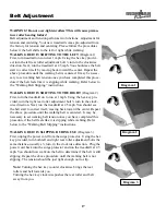
Page 17: ...to run at 1 mph Using the hex key pro vided turn the right rear roller adjustment bolt turn in the clock wise direction Next run the treadmill at 2 5 mph You should see the belt start to correct itself moving back toward the center Repeat the above procedure until the walking belt is centered It may be necessary to set walking belt tension once you have completed this procedure if the belt feels l...

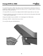
Page 18: ...he steps described here 1 Turn power OFF on the console Do not unplug treadmill Attach the magnet safety key to the console 2 Activate the calibration mode switch by inserting the eraser end of a pencil into the opening in the backside of the console see diagram below 3 Depress the calibration mode switch ONCE CL11 should appear in the TIME window 4 Pressing the SPEED button will activate your cho...

Page 19: ... lift the sides of the walking belt and feel the top surface of the walk ing board as far under as you can reach If you feel signs of silicone no further lubrication is required If it feels dry to the touch lubrication is needed Ironman Fitness recommends Lube N Walk for cleaning and lubricating the treadmill belt and deck Ask your retailer or call Ironman Fitness at 800 750 4766 You may also use ...

Page 20: ...lectrical breaker box and the circuit breaker for the room where the treadmill is located If it has tripped reset or have an electrician replace the breaker in home 3 If the treadmill will not operate please call Ironman Customer Service at 800 750 4766 Treadmill walking belt slows during use 1 Check to make sure the treadmill is securely plugged into an UL listed surge protector rated at 15 amps ...

Page 21: ...Messages E11 Lack of speed feedback data from belt motor Attempt calibration See Calibration Sequence section on page 22 of this Owners Manual for detailed information E22 Under Speed condition detected from the belt motor Attempt calibration See Calibration Sequence sec tion for detailed information E33 Over Speed condition detected from the belt motor Attempt calibration See Calibration Sequence...

Page 22: ...ll toggle options Choose 10 or 16 for KPH mode press Enter 8 CL23 FFF UUU or HHH will be displayed in the Speed window pressing the Speed button will tog gle options Choose UUU press Enter 9 CL24 111 or 222 will be displayed in the Speed window pressing the Speed button will toggle options Choose 222 press Enter 10 CL25 AL1 or AL2 will be displayed in the Speed window pressing the Speed button wil...

Page 23: ...JAM NUT 5 16 18 4 27 406 00051 BOTTOM SHEET 150 220 320t TRI 7 3t 1 80 402 00064 Screw ST4 2 32 2 28 406 00021 MAIN CONSOLE BOX B 1 81 402 00065 Screw ST4 8 16 8 29 406 00022 LEFT TOP HANDLE COVER 1 82 406 00059 SQUARE BUMPER 40 28 6 2 30 406 00023 RIGHT TOP HANDLE COVER 1 83 402 00097 PHILIP SCREW ST4 16 19 31 406 00024 LEFT POCKET BOTTOM 1 84 402 00068 Philip Screw ST4 2x16 117 32 406 00025 RIGH...

Page 24: ...RNESS 1 149 415 00005 MANUAL 150T 1 121 412 00006 MOTOR 12 0049 1 150 402 00092 ALLEN BOLT 2 122 406 00046 FAN MOTOR 1 151 406 00057 POWER CORD SPACER 1 123 413 00013 CONSOLE HARNESS A 3pcs 152 402 00093 GEAR WASHER 1 124 413 00014 SPEED AND INCLINE HARNESS 2 153 402 00098 PHILIP SCREW ST2 9 6 5 6 125 413 00015 EKG HARNESS 2 155 406 00079 BASE BUMPER 28 25 13 2 126 408 00014 FUSE 2 156 402 00012 A...

Page 25: ...Exploded View 25 ...

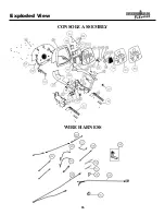
Page 26: ...Exploded View 26 CONSOLE ASSEMBLY WIRE HARNESS ...

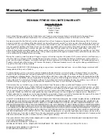
Page 27: ...uties and taxes or any other charges associated with transportation of the parts or Product In addition you are responsible for insuring any parts or Product shipped or returned You assume the risk of loss during shipment You must present Ironman with proof of purchase documents including the date of purchase Any evidence of alteration erasing or forgery of proof of purchase documents will be caus...

Page 28: ...rvice 800 750 4766 Ironman Fitness Products 4009 Distribution Drive Suite 250 Garland TX 75041 www ironmanfitness com Ironman and M dot are registered trademarks of the World Triathlon Corp used here by permission ...

Reviews: