IRIS 216 Manual Download Page 6

4.01 Camera Control Data

IRIS216/316  cameras  are  controlled  via  an  RS485  serial  data 
connection, using a variant  of the Pelco-D  CCTV camera control 
protocol.  The  Pelco-D  protocol  was  designed  to  provide 
accurate  controls  for  a  wide  range  of  standard  CCTV  features, 
such  as  pan,  tilt,  user  preset  features  etc,  but  do  not  include 
features  specific  to  thermal  imaging  cameras  and  other 
extended  features  supported  by  Iris  cameras.  Because  of  this, 
Iris have  mapped  their  product  specific  features  to  certain  user 
preset  commands  and  to  other  modified  Pelco-D  commands. 
This  means  that  Iris  thermal  PTZ  cameras  can  be  controlled 
either  by a dedicated Iris joystick  controller  such  as the IRIS516 
or  IRIS507,  as well  as other control  devices, such  as compatible 
chart-plotters, multi-functional  displays and third  party  joysticks. 
For  further  information  on  compatible  third  party  control 
interfacing  please  contact Iris Innovations. For  certain third party 
interfacing, additional  serial protocol convertors may be required 
where NMEA0183 or NMEA2000 connections are used.

4.02


Cabling Requirements

The  camera  has a  3 meter tail  into which a  50cm  breakout cable 
is  connected.  The  breakout  tail  has  the  following  connections: 
Video  (female  75

Ω

  BNC  connector),  Data  (2  x  bare  wires: 

RS485+  (RED  wire)  and  RS485-  (Black  wire))  and  Power 
(2.5mm  DC  Barrel  Jack  connector).  Individual  video,  data  and 
power  cables can be  run  back  to  the  control  position and power 
distribution  position  or  a  combination  cable  (such  as  IRIS-
COMBPTZ-xx) can  be used. Alternatively, an Active Video  Balun 
set  can  be used to  allow  a  single  CAT5 cable  to  be run.  Please 
note  however  that  although  Baluns  facilitate  the  use  of  CAT5 
cables,  these  should  on  no account be  routed  through  ethernet 
routing  and  switching  hardware  as  this  will  cause  permanent 
damage.  If  Baluns  are  used,  ensure  the  CAT5  cables  are 
managed  completely  separately  from  your  IP  network.  Contact 
Iris Innovations for further details.
Video cables need to be coaxial with an impedance of 75

Ω

 such 

as RG59, URM70 or similar.
Power cables need to be 2 core  DC cable rated at 5A (maximum 
voltage 36VDC)
Data  Cables  need  to  be  twisted  pair  Belden  style  data  cables 
(0.5mm) or equivalent.

4.03 Setting Camera Address

Each  camera  must  have  it

ʼ

s  own  unique  address  so  that  only 

control  data intended for that camera is received and processed 
by  the  camera. If  multiple  cameras had the same  address, they 
would  all  move  together  when  pan  and  tilt  commands  are 
transmitted.
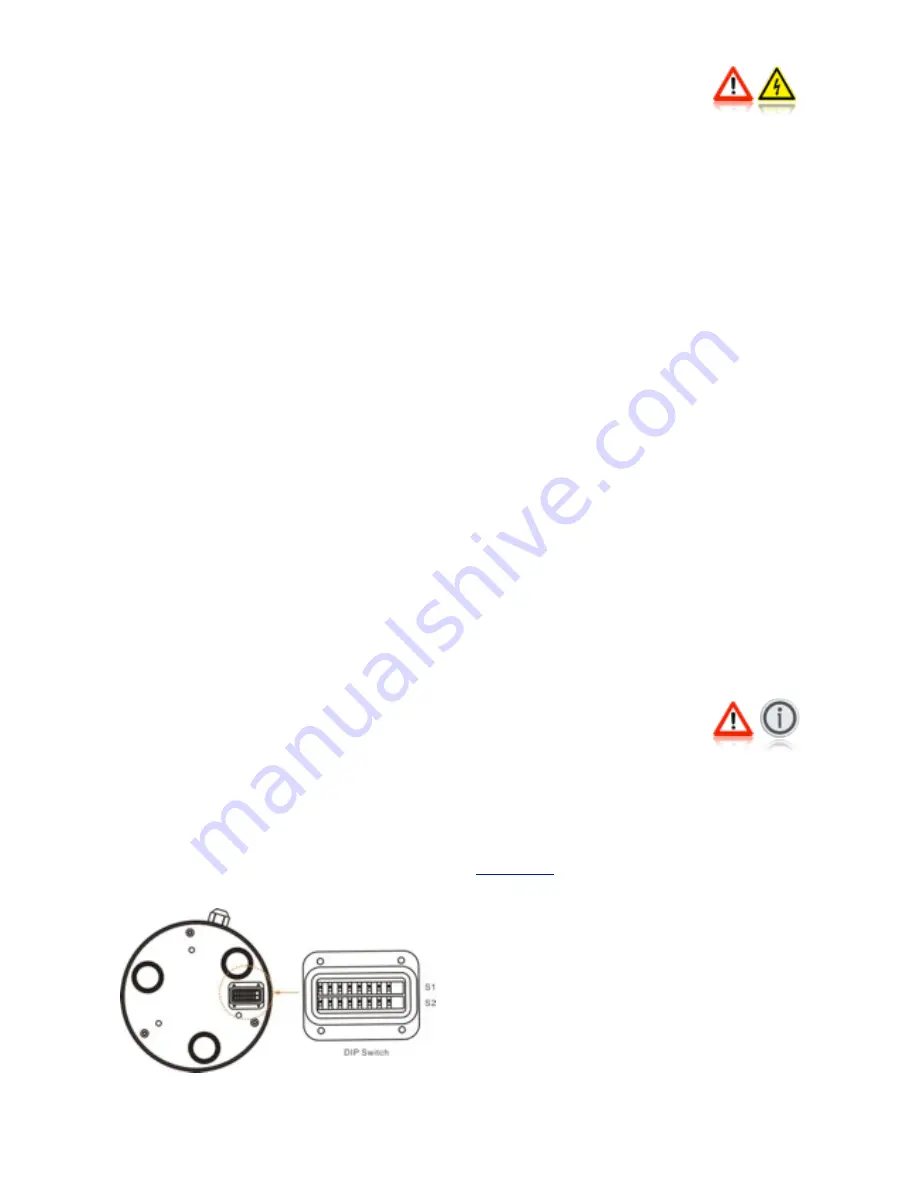
To  set  the  camera  address,  remove  the  DIP  switch  cover  plate 
on  the base of the camera with a  small  cross-head screw driver, 
taking care not to loose the  4  screws or  the rubber 

ʻ

O

ʼ

 seal, and 

set  the  DIP  switches  on  switch  bank  1  accordingly.  A  table 
detailing  the  switch  settings  can  be  found  at  the  end  of  this 
document.

Once  the  desired  address  has  been  set,  carefully  replace  the 
DIP switch cover plate.

4.04 Installation Considerations 

It's  important  to  fully  consider  the  intended  position  of  the 
camera  and  the  desired  fields  of  view  prior  to  installation,  in 
terms of how you  are  going  to get cables to  the position,  will  the 
camera  be  able  to  see  the  appropriate  areas,  will  the  camera 
interfere  with  any  other  fixture  such  as  a  doorway  or  walkway 
once it's fixed in place, or  are there  any  obstructions behind the 
surface  onto  which  the  camera  is  to  be  installed.  It's  strongly 
recommended that if possible  the  camera  should be  temporarily 
powered  up prior  to  final  installation and offered  into  position  so 
that these factors can  be considered  and any possible issue can 
be  addressed  before  holes  are  drilled  and  difficult,  time 
consuming  and  costly  cable  runs  are  attempted.  Check  third 
party  hardware  to  ensure  it  doesn't  effect  the  operation  of  the 
camera and vice versa.

4.05 Protocol Information

DIP  switch  bank  2  is  reserved  for  setting  the  baud  rate  and 
protocol  details.  This  is  factory  set  to  9600  Baud,  Pelco-D 
Protocol,  N-8-1  (No  Parity Bits, 8  Data  Bits, 1 Stop  Bit).  Do  not 
attempt  to  change  these  settings as  they are  locked.  Changing 
the  settings  of  Switch  bank  2  could  result  in  the  camera  not 
responding to data commands.

Full  details  of  the  Pelco-D  control  protocol  can  be  found  at 

www.pelco.com

As well as the standard Pelco-D command  set, Iris cameras use 
their  own  commands  based  on  the  Pelco  protocol  to  call 
features that are specific to the model  or are not covered by the 
Pelco command set. For further details contact Iris Innovations.

Summary of Contents for 216

Page 1: ...216 316 USER GUIDE ...

Page 2: ...TEM EXAMPLES 6 4 01 CAMERA CONTROL DATA 6 4 02 CABLING REQUIREMENTS 6 4 03 SETTING CAMERA ADDRESS 6 4 04 INSTALLATION CONSIDERATIONS 6 4 05 PROTOCOL INFORMATION 7 5 01 HARDWARE INSTALLATION 9 6 01 CONNECTIONS 9 6 02 VIDEO CONNECTIONS 9 6 03 DATA CONNECTIONS 9 6 04 POWERING UP 10 7 01 CONTROLLING THE CAMERA 12 8 01 PROTOCOL LIST 14 9 01 CAMERA ADDRESS TABLE 15 10 01 SPECIFICATIONS 16 BACK COVER CON...

Page 3: ...ositional Indicator 360 Variable Speed Continuous Rotation 210 Variable Speed Tilt Mode Auto Flip Feature to Automatically Correct the Camera Orientation when the Tilt Passes itʼs Tilt Azimuth Video Freeze Feature User Programmable Pattern Tours IRIS216 Model features 44 Greater Resolution then Standard QVGA Cameras IRIS316 features 17µm Pixel Pitch for Superior Picture Clarity Thermal Sensitivity...

Page 4: ...se this product CAUTION Service and Maintenance This product contains no user serviceable parts Please refer all maintenance and repair issues to your authorized Iris Innovations dealer Any unauthoriZed work to the product may affect the warranty CAUTION Care and Cleaning This product is a sensitive piece of electronic imaging equipment and must be handled and treated accordingly Do not drop or sh...

Page 5: ...s offered by most chart plotters and so a video switcher such as the IRIS606 c Camera switcher would be required Video from each camera is routed into the video switcher and the output from the switcher is then routed into a single input of the chart plotter Switching is controlled by a dedicated waterproof keypad connected to the switcher The data wires from each of the controllable cameras along...

Page 6: ... Cables need to be twisted pair Belden style data cables 0 5mm or equivalent 4 03 Setting Camera Address Each camera must have itʼs own unique address so that only control data intended for that camera is received and processed by the camera If multiple cameras had the same address they would all move together when pan and tilt commands are transmitted To set the camera address remove the DIP swit...

Page 7: ...To avoid moisture ingress between the bottom of the BRK P160 fixing plate and the surface onto which the camera is to be attached apply a bead of suitable silicone sealant around the edge of the plate to create a seal Fixing Plate IRIS BRK P160 For mounting onto flat surfaces either standard or hanging orientation Camera Fixing Points 3 x Counter sunk fixing holes for attaching camera to fixing pl...

Page 8: ...g Plate to base of camera M5 x 10mm Countersunk Screws Supplied in 3 positions Fix Mounting Plate to base of camera Cable Entry Route umbilical cable through here Standard or ʻDesktopʼ Orientation The camera is factory set for installation in the ʻStandardʼ orientation as shown here To install in the hanging orientation as shown in the main image above ensure the cameras video output has been set ...

Page 9: ...ect the RS485 wires to a power source as this could permanently damage the camera or controller Observe care when connecting as the RS485 wires are coloured red and black and could be confused for DC power lines Even if the cable connections are made in an internal location or in an area that wouldnʼt usually be exposed to moisture it is recommended that the connections are protected from any poss...

Page 10: ...n the slower it will pan and tilt when commanded and vice versa This greatly improves control accuracy when zoomed in Auto Flip When the camera is tilted past its azimuth the Auto Flip feature is triggered This automatically pans the camera through 180 at full speed Proportional Control is disabled during this procedure to the original pan position and continues the tilt movement as long as the ca...

Page 11: ...ent Scan Modes The camera supports 4 different Scan Modes Once activated tilt and zoom commands are still accepted by the camera but you will not be able to pan the camera until the Scan has been Stopped 45 Auto Scan Camera pans back and forth 22 5 either side of the centre point the position the camera is facing when the scan is activated 90 Auto Scan Camera pans back and forth 45 either side of ...

Page 12: ... 00 E6 CHK Thermal Colour Palettes Mono White Hot Preset 201 FF AD 00 07 00 C9 CHK Mono Black Hot Preset 202 FF AD 00 07 00 CA CHK Redscale Red Hot Preset 203 FF AD 00 07 00 CB CHK Redscale Black Hot Preset 204 FF AD 00 07 00 CC CHK Ironbow Preset 205 FF AD 00 07 00 CD CHK Reverse Ironbow Preset 206 FF AD 00 07 00 CE CHK Greenscale Green Hot Preset 207 FF AD 00 07 00 CF CHK Greenscale Black Hot Pr...

Page 13: ...FF AD 00 07 00 61 CHK Set Camera Safe Position Set Safe Set Preset 232 FF AD 00 03 00 E8 CHK Call Camera Safe Position Call Safe Preset 232 FF AD 00 07 00 E8 CHK Freeze Image Freeze Preset 234 FF AD 00 07 00 EA CHK Un Freeze Image Resume Preset 235 FF AD 00 07 00 EB CHK Scene Mode Off Preset 220 FF AD 00 07 00 DC CHK Day Preset 221 FF AD 00 07 00 DD CHK Night Preset 222 FF AD 00 07 00 DE CHK Fog P...

Page 14: ...F ON OFF OFF OFF OFF 11 ON ON OFF ON OFF OFF OFF OFF 12 OFF OFF ON ON OFF OFF OFF OFF 13 ON OFF ON ON OFF OFF OFF OFF 14 OFF ON ON ON OFF OFF OFF OFF 15 ON ON ON ON OFF OFF OFF OFF 16 OFF OFF OFF OFF ON OFF OFF OFF 17 ON OFF OFF OFF ON OFF OFF OFF 18 OFF ON OFF OFF ON OFF OFF OFF 19 ON ON OFF OFF ON OFF OFF OFF 20 OFF OFF ON OFF ON OFF OFF OFF 21 ON OFF ON OFF ON OFF OFF OFF 22 OFF ON ON OFF ON OF...

Page 15: ...OB mode applies box around hottest object in scene MOB mode applies box around hottest object in scene MOB mode applies box around hottest object in scene MOB mode applies box around hottest object in scene Video Pause Yes Yes Yes Yes Standby Mode Yes Yes Yes Yes Communications Protocol Serial Control RS485 Pelco D Protocol Iris Variant Serial Control RS485 Pelco D Protocol Iris Variant Serial Con...

Page 16: ...wick Hampshire SO31 7GB United Kingdom Tel 44 0 1489 570797 email info boat cameras com web www boat cameras com Iris Innovations Limited USA Suite 130 401 E Las Olas Blvd Fort Lauderdale 33301 Flordida United States of America email info boat cameras com web www boat cameras com ...

Reviews: