IRIS ID IrisAccess iCAM7100S Series Hardware Manual Download Page 4

4

NOTE

NOTE

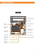
Installation Guidelines

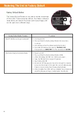
1. Recommended Mounting Information

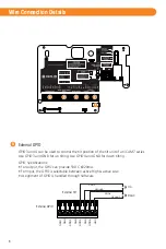
2. General Wiring Requirements

54.3”

(138cm)

61”

(155cm)

This is based 
on the assumption 
that users’ average 
height is 5‘7”(170cm) 

Floor

Bottom of
Mirror

7.01”

(178mm)

8.31”

(211mm)

2.52”

(64mm)

Ethernet network wiring to connect with the network switch for communication.
            

NOTE

The iCAM7 series requires at least the following wires:

IMPORTANT: 

IT IS RECOMMENDED THAT THE IRISACCESS SYSTEM BE PLACED ON A PRIVATE NETWORK 

SEPARATE FROM GENERAL CORPORATE OR PUBLIC ACCESS. SYSTEM PERFORMANCE AND STABILITY MAY BE 
AFFECTED DEPENDING ON AMOUNT OF GENERAL NETWORK TRAFFIC.

The iCAM was designed for indoor use only. This device is not weatherproof and must not be 
exposed to precipitation or extreme temperatures. If it is required to use this product in an 
outdoor or extreme environment, a 3rd Party enclosure may be used to protect the unit from 
exposure to dust, moisture, and extreme temperatures. See www.irisid.com - Support & 
Service for more information. Installation in a extreme environment without proper protection 
may cause permanent damage and void the warranty.

The recommended mounting height for the iCAM7 series is 138cm (54.3inches) from the 
floor to the bottom of the unit. This mounting height can be adjusted to accommodate the 
height of the average user at the installed location.

High amounts of ambient light must be avoided. Intense light sources such as sunlight or 
halogen lamps may reduce the image capture performance of the iCAM which may result in 
an increased “failure to acquire” rate.

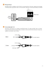
Power Adapter: The optional power adapter (iCAM7-PWR) can be used as the power source 
of the iCAM used for enrollment or other “non-installed” applications. The wires of the 
adapter should not be extended. If the power source is beyond the length of the power 
adapter then an external power source and wiring should be used. Be sure to observe the 
polarity of the adapter wires to the power screw terminals on the iCAM main board.

Power and Wiring: For permanent installation it is recommended to use an external power 
supply and wiring.
• Power Supply: 12-24VDC +/- 10% - Minimum 24 Watts (24VDC @ 1AMP).
• Power Wiring: The recommended wire gauge for the ICU power is 18AWG (1.0 mm) wire.
            Use of a stable power supply and proper gauge wire is required. The wire length voltage 
drop must be accounted for in order to maintain the correct power at the ICU7000-2 unit. For wire 
lengths over 30 feet (9 meters) or if thinner gauge wire is being used (more than 18AWG) then it is 
required that a 24VDC power supply be used to overcome the wire length voltage drop. A 24VDC 
supply with 18AWG (1.0 mm) wire will allow for a distance of up to 200 feet (61 meters).

            For systems consisting of only the iCAM and a computer, an Ethernet cross-over cable 
may be used. 

OR

Summary of Contents for IrisAccess iCAM7100S Series

Page 1: ...1 0 Packing List Required Equipment not included Power Source 12 24 VDC 10 Minimum 24W 12VDC 2AMPS Measured at iCAM unit Uninterruptable Power Supply strongly recommended Network Ethernet Wiring CAT5e Ethernet Cabling or better Ethernet Switch Software Software required depending on Application See www irisid com for details What s in the Box iCAM7 series Hardware Guide L wrench iCAM7 series Hardw...

Page 2: ...Cable Channel Knock out Function Buttons Screw Cap Face Camera Alignment Guide Card Reader optional Speaker Status LED Tripod Socket 1 4 20 1 4 diameter 20 threads per inch Surface Mounting Screw Hole Gang Box Screw Hole Screw Cap Function Buttons Tamper Switch Desktop Stand Hole Installation Plate Camera Unit Interface Panel CCTV Camera optional ...

Page 3: ...l GPIO Relay Output RS232 RS485 RS422 Serial Wiegand Output Input Tamper Switch Wiring Legend Guide Installation Plate Screw RTC Battery Power LED Power Connection Power On Off Switch Ethernet Connection USB 2 0 Bottom Factory Default Button External Speaker Jack ...

Page 4: ... height of the average user at the installed location High amounts of ambient light must be avoided Intense light sources such as sunlight or halogen lamps may reduce the image capture performance of the iCAM which may result in an increased failure to acquire rate Power Adapter The optional power adapter iCAM7 PWR can be used as the power source of the iCAM used for enrollment or other non instal...

Page 5: ... Installation The iCAM7 series unit can be fitted to a surface mount available out of the box recess mount with optional recess mounting kit or optional desktop stand Surface Mounting After opening the interface panel loosen the screw Unscrew the installation plate screw to separate from the installation plate Separate the installation plate by sliding the plate downward 3 Cover Rear Installation ...

Page 6: ...wiring through the installation plate hole i e Power Ethernet etc Attach the installation plate to the wall surface using the appropriate fastener recommended 10 screws and anchors for the wall material Another option is to mount and fasten the installation plate to a previously installed electrical gang box 4 Installation Plate Surface Mount Gang Box Mount Hole Marking Installation Plate ...

Page 7: ...to closed position 9 Remove protective film from RTC battery 6 Before wiring unit confirm the power is in the off position Route and connect the Power and Ethernet wires to iCAM7 series 7 NOTE OFF ON Power on Power Supply Connector Ethernet Cable If connecting any other wiring such as Wiegand GPI O to the iCAM review the following section Wire Connection Details before closing interface panel and ...

Page 8: ...ctable between active High active Low Assignment of GPIO is handled through Software GPIO3 and 4 can be used to control the tilt position of the tilt unit of an iCAM7 series Use GPIO3 and GND for up tilting Use GPIO4 and GND for down tilting External GPIO External Tilt GPIO1 GND GPIO2 GND GPIO3 GND GPIO4 GND GPIO3 GROUND GPIO4 GROUND Up Down ...

Page 9: ...port of computer or access system TX RX TX RX RS485 serial communication port for connection with an access panel or to other computer equipment When configured the Card ID associated with the user is output from the RS485 output port upon a successful identification TX RX TX RX GND RS422 Output RS422 Output To RS422port of computer or access system TX TX RX RX RS422 serial communication port for ...

Page 10: ...changes from Red to Green for an accepted user Relay_2 NC_2 COM_2 NO_2 is typically used to indicate iCAM tamper In this diagram the relay is activated when the iCAM tamper switch is triggered The maximum electrical rating for the relay is 3A at 24VDC RED LIGHT POWER SUPPLY ALARM SYSTEM 24 HOUR ZONE GREEN NC_1 COM_1 NO_1 NC_2 COM_2 NO_2 Wiegand Output Wiegand Specifications Wiegand output uses 3 w...

Page 11: ...um 300mA current to a proximity card reader 12VDC Max 0 3A DATA_0 DATA_1 GND External Speaker Out F To amplified speaker Left signal Ground Right signal 3 5mm Allows for connection of an external amplified speaker This port provides mono or stereo single channel audio of voice prompts and other unit sounds Both the internal and external speakers can operate concurrently To amplified speaker Mono S...

Page 12: ...IP address of an iCAM is 192 168 5 100 default IP you would access the configuration web interface by typing http 192 168 5 100 from an internet browser To login the User ID required when prompted is iCAM7000 The Password is iris7000 The system is case sensitive when entering in your login credentials Once you have connected to the iCAM Configuration Interface settings information and options beco...

Page 13: ...d is presented Picture capture range is 11 15 inches 28 38cm away Self or auto set height adjustment Placing dot over the bridge of nose easily helps alignment Green dot In range Orange dot Out of range 28 38cm Tilt up 35 Degrees Read distance 14inches Tilt down 25 Degrees Read distance 14inches away 11 15 The on unit up down tilt buttons can be used to adjust the tilt angle or an external mounted...

Page 14: ...r at least 10 seconds Stop holding the FDB Do not turn off the power to the unit or remove the network connection for at least 10 minutes the unit will reboot several times on its own during the software reload process When complete the iCAM will have reloaded the software and reset IP Addresses and log in creditenials to the defaults Restoring The Unit to Factory Default The Factory Default Butto...

Page 15: ...15 Memo Serial Number Unit IP Address Installation Date Option 3 Iris Server IP Option 3 Security ID Note ...

Page 16: ... Pop up on screen pin pad Pin Pad High output LED flash for face capture Flash Face camera CMOS 5MP Face Image Camera 32 F 113 F 0 C 45 C Operating Temperature 4 F 203 F 20 C 95 C Storage Temperature Up to 90 non condensing Humidity Control for user defined operations Relays x 2 Iris Face Camera Rotation Angle Communications Inputs Outputs Equipment Supplied with iCAM7 series 35 25 Ethernet LAN WA...

Reviews: