background image


HDC-5004  IP  to  QAM  Modulator  User  Manual 


Date 28. Januar 2020 

BLANKOM-HDC-5004_IP2QAM-modulator-V1.4-RR-01-2020 

3.2.4 Device Grounding 

Connecting the device’s grounding rod to frame’s grounding pole with copper wire. 

3.3 Wire Connections 

3.3.1 Power cord connection 

The power socket is located on the right of rear panel, and the power switch is on the left of front 
panel. User can plug one end of the power cord to the socket and insert the other end to AC power. 
When the device solely connects to protective ground, it should adopt independent way, say, share 
the same ground with other devices. When the device adopts united way, the grounding resistance 
should be smaller than 1Ω. 

Caution: 

Before  connecting  power  cord  to  the  IP  QAM  Modulator,  user  should  set  the  power 

switch to “OFF”.   

3.3.2 Signal and Network Management (NMS) Cable Connection   

The  signal  connections  include  the  connection  of  input  signal  cable  and  the  connection  of  output 
signal cable.    Please use at least CAT 5 STP RJ45 LAN Cable for the management port and CAT 6 DSTP 
for the streaming data ports to avoid electromagnetic influences. For RF cable we recommend double 
shielded Coax. 

Chapter 4: Web NMS Management 

This  device  does  not  support  an  LCD  operation,  and  the  modification  can  only  be  operated  with 
Web NMS by using a standard web-browser. We recommend to use Firefox – latest version.


4.1 Login 

The  factory  default  IP  address  is 

192.168.0.136

  and  users  can  connect  the  device  and  web  NMS 

through this IP address.   
Connect the PC (Personal Computer) and the device with a network cable, and use ping command to 
confirm they are on the same network segment. For instance, the PC IP address is 192.168.99.252, we 
then change the device IP to 192.168.0.xxx (xxx can be 0 to 254 except 136 to avoid IP conflict).   
Launch the web browser an input the device IP address in the browser’s address bar and press Enter. 

We recommend to use the latest Mozilla Firefox browser.


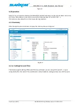
It  will  display  the  Login  interface  as  Figure-1.  Input  the  Username  and  Password  (Both  the  default 

Username and Password are “admin”.


And then click “Login” to start the device setting. 


Summary of Contents for BLANKOM HDC 5004

Page 1: ...HDC 5004 IP to 4 QAM Modulator EDGE QAM User Manual Software Version 1 12 Build 100 Dec 10 2019 Hardware Version 5 40 Web Version 1 03 OS Version 01 01 02 06...

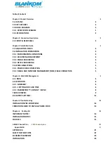
Page 2: ...5 3 3 WIRE CONNECTIONS 5 3 3 1 POWER CORD CONNECTION 5 3 3 2 SIGNAL AND NETWORK MANAGEMENT NMS CABLE CONNECTION 5 Chapter 4 Web NMS Management 5 4 1 LOGIN 5 4 2 OPERATION 6 4 2 1 SUMMARY 6 4 2 1 1 SE...

Page 3: ...BETRIEB 24 WARTUNG 25 REPARATUR 25 VERKAUF 25 ENTSORGUNG 26 INSTALLATION GUIDE FOR F CONNECTORS 27 CONTACT 28...

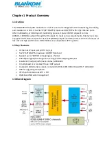
Page 4: ...rt for 4x IP SPTS MPTS output over UDP protocol With the features of low cost and high performance HDM 5004 is very adaptable to IPTV systems 1 2 Key Features 4 Ethernet IP input ports IPTV 1 2 3 4 51...

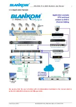
Page 5: ...te 28 Januar 2020 BLANKOM HDC 5004_IP2QAM modulator V1 4 RR 01 2020 1 1 3 1 Application Example We assume that the user is familiar with all abbreviations mentioned in this manual which is written for...

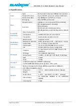
Page 6: ...7 Connection Local remote connection to CAS Modulation Parameters QAM Channel 4 adjacent carrier Modulation Standard DVB C Annex A C and B EN300 429 ITU T J 83A B Symbol Rate 5 0 9 0 Msps 1 kSps steps...

Page 7: ...ssary to check items according to packing list Normally it should include the following items HDC 5004 IP QAM Modulator User s Manual online download from www blankom de Power Cord and grounding wire...

Page 8: ...vice s frame should be no less than 25mm2 3 2 3 Frame Grounding All the machine frames should be connected with protective copper strip The grounding wire should be as short as possible and avoid circ...

Page 9: ...Please use at least CAT 5 STP RJ45 LAN Cable for the management port and CAT 6 DSTP for the streaming data ports to avoid electromagnetic influences For RF cable we recommend double shielded Coax Chap...

Page 10: ...y tables are cross referencing to other tables example EIT and SDT PMT Information can be grabbed from https www dvb org standards 4 2 1 Summary When the login has been confirmed it displays the summa...

Page 11: ...for European NTP Server addresses But first set the time zone please first set time zone than config NTP Server And you are done but your Device need a connection to these NTP addresses Local Gateway...

Page 12: ...output multiplexes TOT offset table can be injected from an IP stream by PID forwarding iof necessary 4 2 2 Parameters TS Config Menu The TS Config Menu sets the basics for your 4 QAM channels From t...

Page 13: ...re in the Input streams please remap them avoiding conflicts To refresh the input program information To refresh the output program information Select one input program first and click this button to...

Page 14: ...ulator V1 4 RR 01 2020 10 Select IGMP Version or OFF not useful Select Input protocol of the stream UDP RTP You can address 1 or many IPTV streams Finally Add and Close this window Your streams shown...

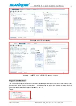
Page 15: ...PID remapping And w o MPTS Input to DVB C Channel 2 output Program Modification The multiplexed program information can be modified by selecting the program in the output area For example when clickin...

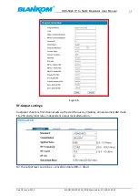
Page 16: ...4_IP2QAM modulator V1 4 RR 01 2020 12 Figure 6 RF Output settings 4 adjacent channels first channel sets up the start frequency middle all need same QAM mode 16 256 and symbol rates independent output...

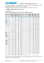
Page 17: ...gures adjacent channel from a start frequency To individually configure the 4 channels set them accordingly in every single config mode The CENELEC Channel Plan would be very helpful See following hin...

Page 18: ...ff must greater than 10 seconds Conditions need to unplug power cord Power cord or socket damaged Any liquid flowed into device Any stuff causes circuit short Device in damp environment Device was suf...

Page 19: ...400 mA By connecting a mains cable the device can become functional without any auxiliary appliances The power supply units are designed for the wide range of 100 230V AC a manual adjustment of the v...

Page 20: ...HDC 5004 IP to QAM Modulator User Manual Date 28 Januar 2020 BLANKOM HDC 5004_IP2QAM modulator V1 4 RR 01 2020 16...

Page 21: ...annel plan Bereich Bands Kanal Channel Kanal frequenzen Channel frequency MHz Mitten frequenz Middle frequency MHz Bild tr ger Picture carrier MHz Ton tr ger Sound carrier MHz Bereich Bands Kanal Chan...

Page 22: ...5 42 646 654 650 00 647 25 652 75 S 14 251 258 254 50 252 25 257 75 43 654 662 658 00 655 25 660 75 S 15 258 265 261 50 259 25 264 75 44 662 670 666 00 663 25 668 75 S 16 265 272 268 50 266 25 271 75...

Page 23: ...5 5 01 3 3E 04 15 75 33 75 5 62 4 2E 04 16 76 32 75 6 31 5 3E 04 17 77 31 75 7 08 6 7E 04 18 78 30 75 7 94 8 4E 04 19 79 29 75 8 91 1 1E 03 20 80 28 75 10 00 1 3E 03 21 81 27 75 11 22 1 7E 03 22 82 26...

Page 24: ...531 47 107 1 75 223 87 0 668 48 108 0 75 251 19 0 841 49 109 0 25 281 84 1 059 50 110 1 25 316 23 1 333 51 111 2 25 354 81 1 679 52 112 3 25 398 11 2 113 53 113 4 25 446 68 2 660 54 114 5 25 501 19 3...

Page 25: ...te gem allen Bestimmungen und Gesetzen des Landes erfolgen Advertencia Al deshacerse por completo de este producto debe seguir todas las leyes y reglamentos nacionales Attention La mise au rebut ou le...

Page 26: ...laid safely Cables and power supply cables must not be damaged or crushed by any objects Furthermore ensure that cables are not laid in the immediate vicinity of sources of heat e g radiators other e...

Page 27: ...evice is only permitted to be connected to the power and operated when the mains adaptor cover is installed This also applies when you clean the device or work on the connections Danger Repairs on the...

Page 28: ...m gliche Sch den am Ger t sowie Brandgefahr durch berhitzung Gew hrleisten Sie einen Mindestabstand von 20cm um das Ger t zu anderen Gegenst nden Gefahr Der Montage bzw Aufstellort mu eine sichere Ve...

Page 29: ...onnenschein Feuer oder dergleichen ausgesetzt werden Explosionsgefahr Warnung Verwenden Sie nur das Zubeh r des Herstellers oder Zubeh r mit identischen technischen Eigenschaften Warnung Bei optischen...

Page 30: ...s Ger t entsprechend den geltenden umweltrechtlichen Bestimmungen Elektrische und elektronische Ger te d rfen nicht in den Hausm ll Vorsicht Entsorgen Sie Batterien falls vorhanden entsprechend den ge...

Page 31: ...be placed on top of the power supply unit Das Netzger t darf nicht Tropf oder Spritzwasser ausgesetzt sein The power supply unit must not be exposed to dripping or splashing water Der Netzstecker mus...

Page 32: ...or V1 4 RR 01 2020 28 Contact IRENIS GmbH Hauptstr 29 31171 Nordstemmen Germany Phone 49 5069 4809781 IRENIS technical hotline VoIP 49 5069 4399 860 or 8601 Managing Director Dipl Ing Murad nol Commer...

Reviews: