74/83
VII. I/O Configuration
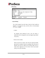
1. I/O Connection
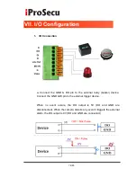
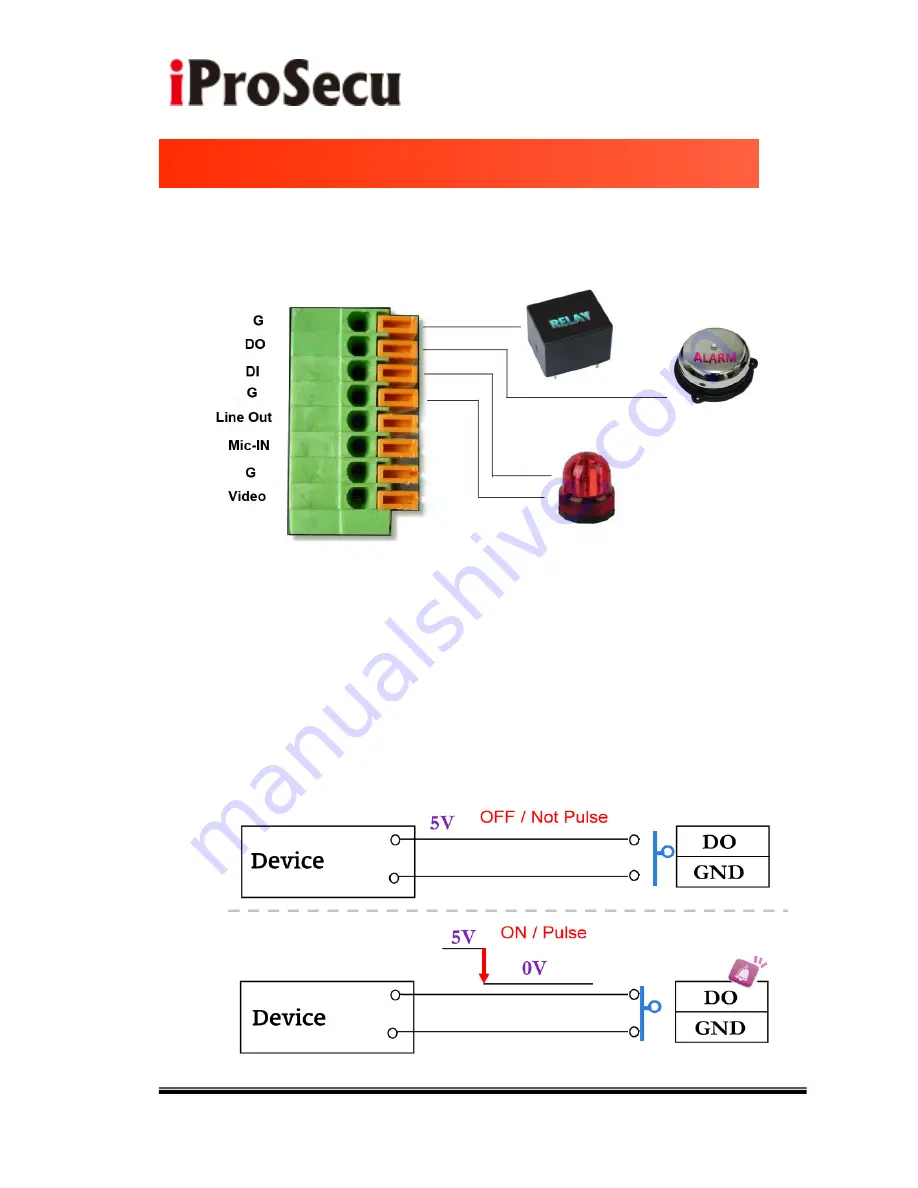
a. Connect the GND & DO pin to the external relay (buzzer) device.
Connect the GND & DI pin to the external trigger device.
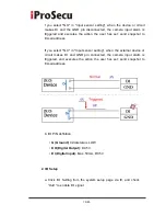
When no event occurs, the DO output is 5V (DO and GND are
disconnected). When the camera detects any event it triggers the external
alarm; the DO output is 0V (DO and GND are connected).
I
Summary of Contents for iDC-1DCF
Page 1: ...1 83 User Manual IP VANDAL DOME CAMERA iDC 1DCF ...
Page 53: ...53 83 ...

