100
Over
O
v
e
r
1
0
9
4
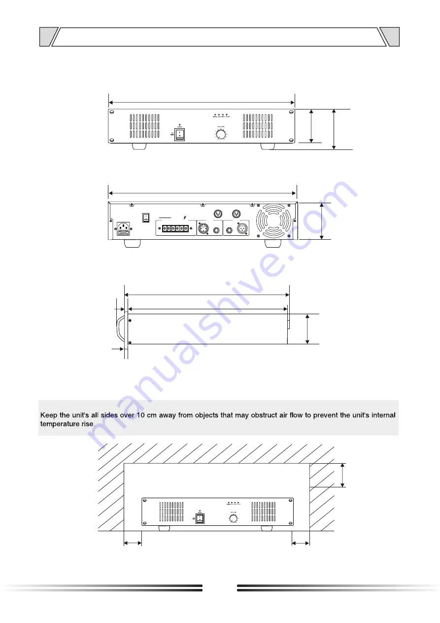
11. DIMENSIONAL DIAGRAM
8
323
317
436
6
25
484
UNIT :mm
16
GND
LIFT
INPUTS
LINK
COM 4-16
¦
70V 100V
OUTPUTS
COM
2
3
XLR BAL1-GND2-HOT+3-COLD-
Page 1: ...1C240 Please follow the instructions in this manual to obtain the optimum results from this unit We also recommend that you keep this manual handy for future reference ON OFF POWER CLIP TEMP PROT SIGN...
Page 2: ...CONNECTIONS 8 6 OPERATION GUIDANCE 6 1 9 6 2 9 6 3 10 6 4 POWER SUPPLY INPUT 10 6 5 SPEAKER OUTPUTS 4 16 70V 100V 11 7 12 8 APPLICATIONS 13 9 BLOCK DIAGRAM 14 10 SPECIFICATIONS 15 11 DIMENSIONAL DIAGR...
Page 3: ...as doing so may result in fire or electric shock Be sure to replace the unit s terminal cover after connection completion Because high voltage is applied to the speaker terminals never touch these te...
Page 4: ...ock When the Unit is in Use Do not place heavy objects on the unit as this may cause it to fall or break which may result in personal injury and or property damage In addition the object itself may fa...
Page 5: ...aker matching A master volume control is included Complete protection includes clip short circuit high temp and overload Indications for power signal clip protection and temp 2 GENERAL DESCRIPTION 1 R...
Page 6: ...ling down 4 PROT The protection indicator will be light on when the constant output is 160 higher than the rated output the output will be cut to protection the amplifier from damage This indicator wi...
Page 7: ...LINK OUTPUT 6 35TRS Balanced or unbalanced output music signal unbalanced output use of non equilibrium 6 35TRS jack 13 LINE CASCADE OUTPUT CORLEONE SOCKET XLR output signal of power amplifier 14 FAN...
Page 8: ...5 CONNECTIONS SPEAKER CONNECTIONS 70V 4 16 100V 4 16 LINE 70V COM 70V LINE 20 100V LINE IPA 1C240 42 IPA 1C240 100V 70V 4 16 COM 4 16 100V 70V COM 4 16 8...
Page 9: ...10 0 1 2 3 4 5 6 7 8 9 10 0 1 2 3 4 5 6 7 8 9 10 0 1 2 3 4 5 6 7 8 9 10 0 1 2 3 4 5 6 7 8 9 10 0 1 2 3 4 5 6 7 8 9 10 0 1 2 3 4 5 6 7 8 9 10 0 4 3 2 1 0 1 2 3 4 5 5 1 2 3 4 5 6 7 8 9 10 0 4 3 2 1 0 1...
Page 10: ...er for more loudspeaker connection The line output volume level is controlled by front panel knobs Notice please minimum the volume knob to MIN position when line output is operated to avoid electrici...
Page 11: ...ce speaker connection and low impedance speaker output only for low impedance speaker connection Speaker total power output shall be no higher than 80 percent of the amplifier rated power output Notic...
Page 12: ...output if the LED is not ligh ting please check the input circuit When you start the machine it will run into auto checking condition its protection LED yellow will shine 3 seconds If the protection...
Page 13: ...INPUT MIC2 MIC3 LINE INPUT OUTPUT COM 4 16 70V 100V REC LINE 10 LINE 9 LINE 8 LINE 7 LE FT RIG HT MIC INPUTS MIC LINE INPUTS 220V 50Hz MAX 9 9W P T T 1 2 3 4 5 6 7 8 9 10 INSIDE AC DC FUSE 220VAC DC P...
Page 14: ...9 BLOCK DIAGRAM EB PA 100V 70V CH1 LINK CH1 INPUTS TO 4 16 COM POWER Z 50Hz 230V PT 14...
Page 15: ...0V 100V 775mV 0dB 50Hz 18KHz Better than 105dB Less than 1 at 1KHz 1 3 rated power Power switch volume control Power clipping Signal protect and high AC fuse short circuit clipping and high temperatur...
Page 16: ...00 Over Over 100 94 11 DIMENSIONAL DIAGRAM 84 84 323 317 88 436 100 Over 6 25 484 UNIT mm UNIT mm 16 GND LIFT INPUTS LINK COM 4 16 70V 100V OUTPUTS COM COM INPUTS LINK 1 2 3 XLR BAL 1 GND 2 HOT 3 COLD...
Page 17: ...PUBLIC ADDRESS SYSTEM PUBLIC ADDRESS SYSTEM VersionV0 1...