


ES50-ES100
Effluent Pumps
OPERATION MANUAL
Dated: 11/02/2016
Document Name: ES50-ES100_OM
Page 6 of 12
Register your product at www.ionproducts.net
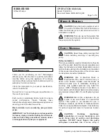
Submergence
The pump should always be operated in the
submerged condition. The minimum sump liquid level
should never be less than above the pump’s motor,
unless very briefly.
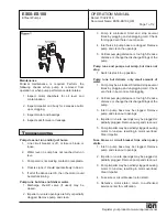
Discharge Piping
Install discharge piping or hose assembly to the pump.
Discharge piping should be as short as possible and
sized no smaller than the pump discharge. Do not
reduce the discharge pipe size below that which is
provided on the pump. Both a check valve and a shut-
off valve are recommended for each pump. The check
valve is used to prevent backflow into the sump. PVC
pipe along with plastic check valve and shut-off valve
are recommended.
Install check valve 12” above pump discharge.
The
shut-off valve is used to manually stop system flow
during pump servicing.
Drill a 1/8” hole in the discharge
pipe below the check valve
approximately 5” from end
nearest volute and oriented towards the pump body.
Control Panel
Single phase series sewage pumps DO NOT require
a control panel, but do require a level controlwith a
piggy back plug,
See Figure 1, Page 7.
Motor
Each motor is provided with heat sensor thermostats
attached directly to the motor windings. The
thermostats open if the motor windings see excessive
heat and, in turn, open the motor contactor in the
control panel when used, breaking the power to
the pump. When the motor is stopped due to an
overheated condition, it will not start until the motor
has cooled.
P
re
-o
PeratIon
Check Voltage And Phase
Before operating pump, check to make sure that
voltage and phase information stamped on the pump’s
identification plate matches the available power.
Check Pump Rotation
Before putting pump into service for the first time,
the motor rotation must be checked. Improper motor
rotation can result in poor pump performance and can
damage the motor and/or pump.
Identification Plate
Note the numbers on the pumps identification plate
and record in this manual for future reference.
CAUTION: Electrical Connections
Turn circuit breaker off before plugging or
unplugging the switch and/or pump.
Piggy-Back Plug
Plug the level control plug into a 115V receptacle, then
plug the pump into the piggy-back plug.
See Figure
1, Page 7.
It is recommended that this circuit have
a 15 AMP breaker. One cycle of operation should
be observed, so that any potential problems can be
corrected.
It is recommended that the level control float should
be set to insure that the liquid in the sump never
drops below the top of the motor housing. The level
control should have adequate clearance so it cannot
hang up in it’s swing and that the pump is completely
submerged when the level control is in the “Off ”
mode. Minimum tether length is 3.50”.
By adjusting the cord tether the control level can be
changed. DO NOT USE THE POWER CABLE TO
LIFT PUMP.
Pump-Down Test
Be sure pump has been plugged in, lowered into
the basin or sump, check the system by filling with
liquid and allowing the pump to operate through its
pumping cycle. The time needed to empty the system,
or pump-down time along with the volume of water,
should be recorded.
Thermal Protection
The normally closed (N/C) over temperature sensor
is embedded in the motor windings and will detect
excessive heat in the event an overload condition
occurs.
The thermal sensor will trip when the windings
become too hot and will automatically reset when the
pump motor cools to a safe temperature.
In the event of an over temperature, the source of
this condition should be determined and repaired
immediately. Thermal protection shall not be used as a
motor overload device.