
18
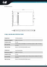
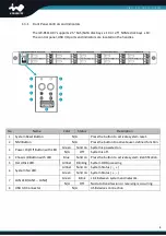
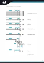
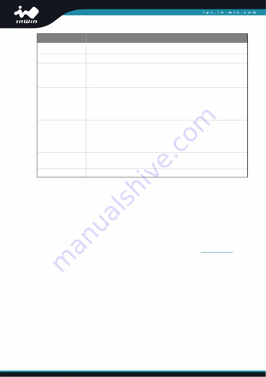
Location
Description
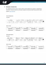
Disk1 ~ Disk10
Connecting SATA/SAS HDD/SSD or NVMe SSD.
JD1
MCU Programming Header
JM3
Setting Function
1 FAIL LED +
2 FAIL LED –
JM2
Setting Function
1-2 Shunted SGPIO Enabled
2-3 Shunted SGPIO Disabled
Not Set Auto
JM1
Pin Function
1 PWM input
2 RPM output
3 GND
FAN1 ~ FAN12
Connect to fan modules.
The backplane supports up to 12 fan modules.
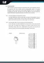
NVME1 ~ NVME10 NVMe interfaces connect to NVMe HBA.
4
Compatibility Lists
To reach the best performance and avoid system failure, InWin strongly recommends customers
to choose the components from InWin’s compatibility list. All the components are tested in
InWin’s lab, and assured the components are compatible with InWin’s chassis. You can
download the latest updated device compatibility list from InWin’s website:
Summary of Contents for IW-RS110-07
Page 3: ...4 Compatibility Lists 18 5 Q A 19 6 Technical Support 20 ...
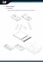
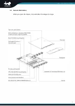
Page 10: ...7 1 3 General Information When you open the chassis it should reflect the diagram s image ...
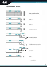
Page 14: ...11 650W Single PSU Cable Information Length Unit mm ...
Page 15: ...12 750W Redundant PSU Cable Information Length Unit mm ...


