InWin IW-MS08-A User Manual Download Page 10

10

● 

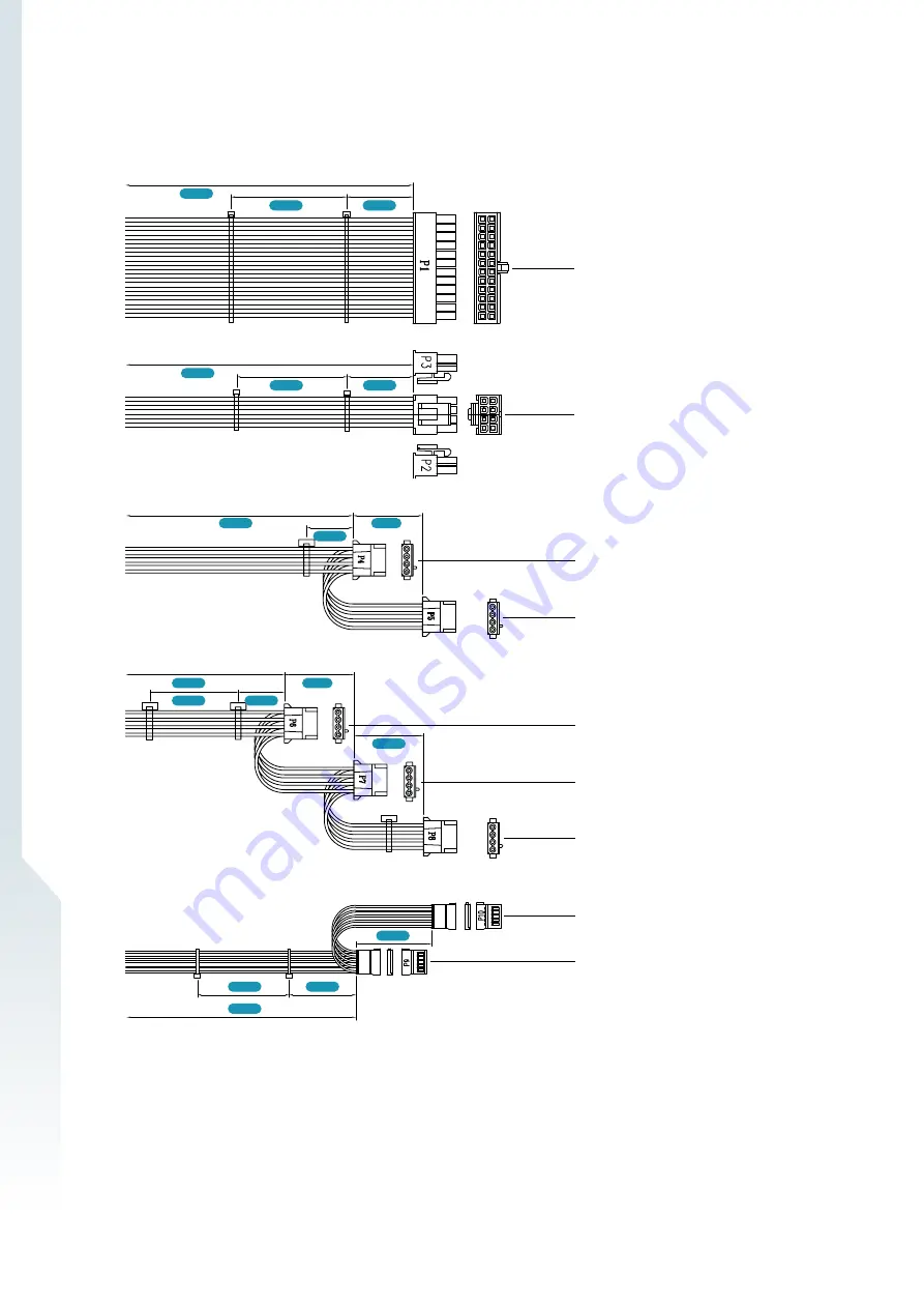
500W single PSU Cable Information

24-Pin Main Motherboard

8-Pin Main Motherboard

4-Pin BP

4-Pin BP

4-Pin BP

4-Pin BP

4-Pin 2.5” HDD BP

SATA Power 2.5” HDD

SATA Power 2.5” HDD

150mm

150mm

150mm

150mm

150mm

150mm

350mm

200mm

200mm

400mm

50mm

50mm

150mm

450mm

300mm

450mm

700mm

700mm

Summary of Contents for IW-MS08-A

Page 1: ...User Manual IW MS08 A...

Page 2: ...designed to operate in a typical office environment The location should be clean dry and free of airborne particles It should be placed in a well ventilated room and away from sources of heat includin...

Page 3: ...to close open or bypass part of an electronic circuit Jumpers on InWin backplanes have a small tab on top that you can pick up with your fingertips Grip the jumper carefully and plug the jumper to co...

Page 4: ...4 When you open the IW MS08 A box the contents should include the following 1 1 Box Contents 1 Product Introduction...

Page 5: ...1 b Rear Plate Cover x 1 c Countersunk Flat Head Screws x 2 d Countersunk Screws x 4 e Oval Head Screws x 4 2 Motherboard Standoffs x 11 3 Countersunk Screws x 35 4 Internal 2 5 HDD Screws x 4 8 Redun...

Page 6: ...s image 1 3 General Information Micro ATX Mini ITX M B Supported 80 x 25 mm PWM Fan x 2 Front Bezel with Lock 80 x 25 mm PWM Fan x 2 4500 RPM Slim ODD x 1 3 5 Floppy Disk Bay x 1 Hot swap 2 5 3 5 x 8...

Page 7: ...n System is powered on N A Off System is off 2 System Reset N A N A Press the button to reset system 3 USB3 0 Connector N A N A USB devices connection 4 LAN LED Amber Blinking Link between system and...

Page 8: ...mounted redundant single or Flex PSUs 2 System I O Depends on M B Specifications The I O shield should come with the motherboard or is provided by motherboard vendors 3 4 Full Height PCI E Slots The s...

Page 9: ...heir desired application For a quick installation video please visit IW MS08 A Hardware Installation 300W redundant PSU Cable Information 2 1 Installation Guide 2 1 1 Power Supply Cable Information 2...

Page 10: ...Pin Main Motherboard 8 Pin Main Motherboard 4 Pin BP 4 Pin BP 4 Pin BP 4 Pin BP 4 Pin 2 5 HDD BP SATA Power 2 5 HDD SATA Power 2 5 HDD 150mm 150mm 150mm 150mm 150mm 150mm 350mm 200mm 200mm 400mm 50mm...

Page 11: ...50mm 150mm 750mm 150mm 150mm 400mm 24 Pin Main Motherboard 8 Pin Main Motherboard 4 Pin BP 4 Pin BP 4 Pin BP 4 Pin BP 4 Pin 2 5 HDD BP SATA Power 2 5 HDD SATA Power 2 5 HDD 150mm 730mm 750mm 300mm 150...

Page 12: ...tions You can find the pin function and location information from your motherboard s user guide 2 2 2 Connecting Backplane through SAS Connectors If the LED power connector on the motherboard is 3 pin...

Page 13: ...best performance and avoid system failure InWin strongly recommends users to choose the components from InWin s compatibility list All the components are tested in InWin s lab and assured the componen...

Reviews: