background image

Goodrive100-PV Series Solar Pumping VFD                                                          Options and use


67 

A.3 Cables 

A.3.1 Power cables 

Dimension the input power and motor cables according to local regulations. 

Note: 

A  separate  PE  conductor  is  required  if  the  conductivity  of  the  cable  shield  is  not 

sufficient for the purpose.


A.3.2 Control cables 

The relay cable needs the cable type with braided metallic screen. 

Keypads need to be connected with network cables. The network cables must be shielded in 

complicated electromagnetic environments. 

Communication cables must be shielded twisted pairs. 

Note:   

  Run analog and digital signals in separate cables. 

  Check  the  insulation  of  the  input  power  cable  according  to  local  regulations  before 

connecting to the drive. 

Recommended power cables for standard VFD models   

Model


Recommended cable size 

(mm

2

Terminal 

screw 

Tightening 

torque 

(Nm) 

(+)/(-), R/S/T, U/V/W 

PE 

GD100-0R4G-S2-PV 

1.5 

1.5 

M4 

0.8 

GD100-0R7G-S2-PV 

1.5 

1.5 

M4 

0.8 

GD100-0R4G-SS2-PV 

1.5 

1.5 

M4 

0.8 

GD100-0R7G-4-PV 

1.5 

1.5 

M4 

0.8 

GD100-1R5G-4-PV 

1.5 

1.5 

M4 

0.8 

GD100-2R2G-4-PV 

1.5 

1.5 

M4 

0.8 

GD100-1R5G-S2-PV 

2.5 

2.5 

M4 

0.8 

GD100-2R2G-S2-PV 

2.5 

2.5 

M4 

0.8 

GD100-0R7G-SS2-PV 

2.5 

2.5 

M4 

0.8 

GD100-1R5G-SS2-PV 

2.5 

2.5 

M4 

0.8 

GD100-2R2G-SS2-PV 

2.5 

2.5 

M4 

0.8 

GD100-004G-4-PV 

2.5 

2.5 

M4 

1.2–1.5 

GD100-5R5G-4-PV 

2.5 

2.5 

M4 

1.2–1.5 

GD100-1R5G-2-PV 

2.5 

2.5 

M4 

1.2–1.5 

Summary of Contents for GD100-004G-2-PV

Page 1: ...Solar Pumping VFD Goodrive100 PV Series ...

Page 2: ...6 Function parameters 22 6 1 Common function parameters for solar pumping control 22 6 2 Parameters of special functions 41 7 Fault diagnosis and solution 59 Appendix A Options and use 65 A 1 Boost module 65 A 2 GPRS module and monitoring APP 66 A 3 Cables 67 A 4 Reactors 69 A 5 Filters 70 Appendix B Recommended solar modules 71 B 1 Recommended configuration for solar pumping VFDs 71 B 2 Recommend...

Page 3: ... Qualified electricians People working on the device should take part in professional electrical and safety training receive the certification and be familiar with all steps and requirements of installing commissioning operating and maintaining the device to avoid any emergency 1 2 Warning symbols Warnings caution you about conditions which can result in serious injury or death and or damage to th...

Page 4: ...3 1 Delivery and installation Please install the VFD on fire retardant material and keep the VFD away from combustible materials Do not operate on the VFD if there is any damage or components loss to the VFD Do not touch the VFD with wet items or body otherwise electric shock may occur Note Select appropriate moving and installing tools to ensure a safe and normal running of the VFD and avoid phys...

Page 5: ...y to run it again before utilization Cover the front board before running otherwise electric shock may occur 1 3 3 Maintenance and replacement of components Only qualified electricians are allowed to perform the maintenance inspection and components replacement of the VFD Disconnect all power supplies to the VFD before the terminal wiring Wait for at least the time designated on the VFD after disc...

Page 6: ...designation label on the outside of the package to verify that the name plate is of the correct type If not please contact with local dealers or offices 5 Check to ensure the accessories including user s manual and control keypad inside the device is complete If not please contact with local dealers or offices 2 2 Name plate Figure 2 1 Name plate Note This is the example of Goodrive100 PV standard...

Page 7: ...andard VFD is IP20 but this field is not displayed Industrial code Industrial code PV stands for solar pumping 2 4 Product specifications Model SS2 S2 2 4 AC input voltage V 220 15 240 10 1PH 220 15 240 10 3PH 380 15 440 10 3PH Max DC voltage V 440 440 440 800 Start up voltage V 200 200 200 300 Lowest working voltage V 150 150 150 250 Recommended DC input voltage range V 200 400 200 400 200 400 30...

Page 8: ...D100 5R5G 2 PV 5 5 25 20 30 GD100 7R5G 2 PV 7 5 33 30 40 4 model 3PH 380V 0 75 200kW GD100 0R7G 4 PV 0 75 3 4 2 5 9 GD100 1R5G 4 PV 1 5 5 0 4 2 9 GD100 2R2G 4 PV 2 2 5 8 5 5 12 GD100 004G 4 PV 4 0 13 5 9 5 16 5 GD100 5R5G 4 PV 5 5 19 5 14 23 9 GD100 7R5G 4 PV 7 5 25 18 5 30 6 GD100 011G 4 PV 11 32 25 39 2 GD100 015G 4 PV 15 40 32 49 GD100 018G 4 PV 18 5 47 38 50 GD100 022G 4 PV 22 51 45 60 GD100 0...

Page 9: ... installation 3 1 1 Installation environment The installation environment is the safeguard for a full performance and long term stable functions of the VFD Check the installation environment as follows Environment Conditions Installation site Indoor Environment temperature The ambient temperature of VFD is 10 50 while air temperature change should be less than 0 5 per minute The VFD will be derate...

Page 10: ...isolation transformer on the input end of the VFD When the altitude exceeds 3000m but is lower than 5000m contact our company for technical consultation Do not use the VFD at an altitude higher than 5000m Vibration 5 8m s2 0 6g Installation direction The VFD should be installed on an upright position to ensure sufficient cooling effect Note Goodrive100 PV series VFDs should be installed in a clean...

Page 11: ...ort wall mounting and flange mounting Flange Figure 3 2 Installation manners 1 Mark the locations of installation holes For details about the holes see the VFD dimension diagram in the appendix 2 Fix the screws or bolts into the marked locations 3 Lean the VFD against the wall 4 Fasten the tightening screws on the wall 3 2 Standard wiring 3 2 1 Terminals of main circuit The figure below shows the ...

Page 12: ...ation box special for PV must be used When the distance between the PV input component and VFD exceeds 10 meters type II surge protection devices must be configured at the DC side When the distance between the pump and VFD exceeds 50 meters it is recommended to configure output reactors See appendix A 4 for the output reactor model selection The VFD automatically runs after being powered on If par...

Page 13: ...tput models 1 Generally the output terminals U and W of the VFD connect to the phase cables of the single phase motor 2 If the single phase pump cannot be started the two phase control method must be used and the start up and running capacitors if any of the motor must be removed The figure below shows the internal wiring of the common single phase motor In the figure L1 L2 C1 and C2 indicate the ...

Page 14: ...inals of control circuit Functions of control terminals Category Terminal symbol Terminal name Terminal function Power supply 24V 24V power supply It provides the power of 24V 10 and maximum current of 200mA It functions as the working power supply of digital input and output or externally connects to the sensor power supply COM Common terminal Digital input S1 Forced switch to power frequency Ter...

Page 15: ...se algorithm A low electrical level corresponds to the two phase algorithm Communication RS485 RS485 485 communication 485 communication terminals using the Modbus protocol 422TX 422TX 422RX 422RX 422 communication Communication terminals special for the boost module Relay output RO1A ROA Normally open contact of relay 1 1 Contact capacity 3A AC250V 1A DC30V 2 They cannot be used for high frequenc...

Page 16: ...cessary to connect the keypad to other external device you can use the standard RJ45 cable with crystal head as the external extension cable Figure 4 1 Keypad diagram for VFDs 2 2kW 1 2 4 3 PRG ESC DATA QUICK JOG SHIFT RUN STOP RST RUN TUNE FWD REV LOCAL REMOT TRIP HZ A V RPM Figure 4 2 Keypad diagram for VFDs 4kW Note External keypads can be configured for VFDs 2 2kW The keypads of VFDs 4kW can b...

Page 17: ...tion terminals operation and remote communication control LED off means that the VFD is in the keypad operation state LED blinking means the VFD is in the terminals operation state LED on means the VFD is in the remote communication control state TRIP LED for faults LED on when the VFD is in the fault state LED off in normal state LED blinking means the VFD is in the pre alarm state 2 Unit LED Mea...

Page 18: ...data or function code progressively SHIFT Right shift key Move right to select the displaying parameter circularly in stopping and running mode Select the parameter modifying digit during the parameter modification RUN Run key This key is used to operate on the VFD in key operation mode STOP RST Stop Reset key This key is used to stop in running state and it is limited by function code P07 04 This...

Page 19: ... the keypad will display the running parameters RUN TUNE LED on the keypad is on while the FWD REV is determined by the current running direction which is as shown in figure 4 2 In the running state there are 6 parameters that can be displayed They are running frequency set frequency bus voltage output voltage output current and rotating speed SHIFT can shift the parameters from left to right QUIC...

Page 20: ...NT will save the set parameters into the control panel and then return to the second level menu with shifting to the next function code automatically while pressing PRG ESC will directly return to the second level menu without saving the parameters and keep staying at the current function code Under the third level menu if the parameter has no flickering bit it means the function code cannot be mo...

Page 21: ...on code editing state 0 0 0 0 0 will be displayed Unless using the correct password the operators cannot enter it The units place is blinking PRG ESC PRG ESC PRG ESC PRG ESC DATA ENT DATA ENT DATA ENT All digits are blinking The units place is blinking The units place is blinking The units place is blinking The units place is blinking Note When setting the value you can press and to modify the val...

Page 22: ...seconds Check the water yield of the pump If the water yield is normal the trial run is successful If the water yield is under the normal value exchange any two motor cables connect the cables and perform trial run again 5 3 Parameter settings The VFD automatically runs by default once being powered on If you want to set parameters press QUICK JOG within 10 seconds since the VFD power on to switch...

Page 23: ...ge differential value appropriately c For single phase motors with two phase control capacitor removing The maximum voltage needs to be less than 1 1 6 of the bus voltage It is recommended to set the rated voltage P02 04 less than 200V or limit the maximum voltage output by multi dot V F curve Observe the currents of the windings through P17 38 and P17 39 the switched current is the combination cu...

Page 24: ...ault Modify P00 Group Basic function group P00 00 Speed control mode 0 SVC 0 No need to install encoders Suitable in applications which need low frequency big torque for high accuracy of rotating speed and torque control Relative to mode 1 it is more suitable for the applications which need small power 1 SVC 1 1 is suitable in high performance cases with the advantage of high accuracy of rotating ...

Page 25: ...n running state to make the VFD coast to stop 1 Terminal running command channel LOCAL REMOT flickering Carry out the running command control by the forward rotation reverse rotation and forward jogging and reverse jogging of the multi function terminals 2 Communication running command channel LOCAL REMOT on The running command is controlled by the upper monitor via communication P00 03 Max output...

Page 26: ...ower limit frequency if the set frequency is lower than the lower limit Note Max output frequency Upper limit frequency Lower limit frequency Setting range 0 00Hz P00 04 Upper limit of the running frequency 0 00Hz P00 11 ACC time 1 ACC time means the time needed if the VFD speeds up from 0Hz to the Max output frequency P00 03 DEC time means the time needed if the VFD speeds down from the Max outpu...

Page 27: ...r two of the motor lines U V and W The motor rotation direction can be changed by QUICK JOG on the keypad Refer to parameter P07 02 Note When the function parameter comes back to the default value the motor s running direction will come back to the factory default state too In pump application scenarios the VFD cannot run in the reverse direction This function code cannot be modified 2 Forbid to r...

Page 28: ...inductance P00 18 Function restore parameter 0 No operation 1 Restore the default value 2 Clear fault records Note The function code will restore to 0 after finishing the operation of the selected function code Restoring to the default value will cancel the user password Use this function with caution 0 P01 Group Start up and stop control P01 08 Stop mode 0 Decelerate to stop After the stop comman...

Page 29: ... Reserved 0 P02 01 Rated power of asynchronous motor 0 1 3000 0kW Set the parameter of the asynchronous motor In order to ensure the controlling performance set the P02 01 P02 05 according to the name plate of the asynchronous motor GD100 PV series VFDs provide the function of parameter autotuning Correct parameter autotuning comes from the correct setting of the motor Depend on model P02 02 Rated...

Page 30: ...D will decrease Note Resetting the rated power P02 01 of the motor can initialize the motor parameters P02 02 P02 10 P02 06 Stator resistor of asynchronous motor 0 001 65 535Ω After the motor parameter autotuning finishes the set values of P02 06 P02 10 will be updated automatically These parameters are basic parameters controlled by vectors which directly impact the Depend on model P02 07 Rotor r...

Page 31: ... GD100 PV series motor 1 to meet the need of different loads 0 Straight line V F curve applying to the constant torque load 1 Multi dots V F curve 2 Torque stepdown characteristic curve 1 3 order 3 Torque stepdown characteristic curve 1 7 order 4 Torque stepdown characteristic curve 2 0 order Curves 2 4 apply to the torque loads such as fans and water pumps Users can adjust according to the featur...

Page 32: ...he output voltage for the features of low frequency torque P04 01 is for the Max output voltage Vb P04 02 defines the percentage of closing frequency of manual torque to fb Torque boost should be selected according to the load The bigger the load is the bigger the torque is Too big torque boost is inappropriate because the motor will run with over magnetic and the current of the VFD will increase ...

Page 33: ...e is high overtemperature and burning may occur and the overcurrent stall and protection may occur to the VFD Output voltage Output frequency Hz V1 V2 V3 f1 f2 f3 100 0 b fb Setting range of P04 03 0 00Hz P04 05 Setting range of P04 04 0 0 110 0 rated voltage of motor1 Setting range of P04 05 P04 03 P04 07 Setting range of P04 06 0 0 110 0 rated voltage of motor1 Setting range of P04 07 P04 05 P02...

Page 34: ... be set to the rated slip frequency of the motor which is counted as below f fb n p 60 Of which fb is the rated frequency of the motor its function code is P02 01 n is the rated rotating speed of the motor and its function code is P02 02 p is the pole pair of the motor 100 0 corresponds to the rated slip frequency f Setting range 0 0 200 0 0 0 P04 34 Two phase control selection of single phase mot...

Page 35: ...frequency setting DOWN 12 Cancel the frequency change setting 13 Shift between A setting and B setting 14 Shift between combination setting and A setting 15 Shift between combination setting and B setting 16 Multi step speed terminal 1 17 Multi step speed terminal 2 18 Multi step speed terminal 3 19 Multi step speed terminal 4 20 Multi step speed pause 21 ACC DEC time 1 22 ACC DEC time 2 23 Simple...

Page 36: ...31 Counter trigger 32 Reserved 33 Cancel the frequency change setting 34 DC brake 35 Reserved 36 Shift the command to the keypad 37 Shift the command to terminals 38 Shift the command to communication 39 Pre magnetized command 40 Clear the power 41 Keep the power 42 Forced switch to power frequency input Switching on indicates switching to power frequency input switching off indicates the input mo...

Page 37: ...ls P06 03 Relay RO1 output selection 0 Invalid 1 In operation 2 Forward rotation operation 3 Reverse rotation operation 4 Jogging operation 5 VFD fault 6 Frequency degree test FDT1 7 Frequency degree test FDT2 8 Frequency arrival 9 Zero speed running 10 Upper limit frequency arrival 11 Lower limit frequency arrival 12 Ready for operation 13 Pre magnetizing 14 Overload alarm 15 Underload alarm 16 C...

Page 38: ...em works in PV mode relay output is high P06 05 Polarity selection of output terminals The function code is used to set the pole of the output terminal When the current bit is set to 0 output terminal is positive When the current bit is set to 1 output terminal is negative BIT1 BIT0 RO2 RO1 Setting range 0 F 0 P06 10 Switch on delay of RO1 0 000 50 000s 10 000s P06 11 Switch off delay of RO1 0 000...

Page 39: ...nd reverse rotations Press QUICK JOG to shift the direction of the frequency commands This function is only valid in the keypad commands channels 4 Clear UP DOWN settings Press QUICK JOG to clear the set value of UP DOWN 5 Coast to stop Press QUICK JOG to coast to stop 6 Shift the running commands source Press QUICK JOG to shift the running commands source 7 Quick commissioning mode based on non f...

Page 40: ... 1 P07 04 STOP RST stop function Select the stop function by STOP RST STOP RST is effective in any state for the keypad reset 0 Only valid for the keypad control 1 Both valid for keypad and terminals control 2 Both valid for keypad and communication control 3 Valid for all control modes 1 P07 11 Boost module temperature When the VFD is configured with the boost module this function code displays t...

Page 41: ...3 7 ACC overvoltage OV1 8 DEC overvoltage OV2 9 Constant speed overvoltage OV3 10 Bus undervoltage UV 11 Motor overload OL1 12 VFD overload OL2 13 Input side phase loss SPI 14 Output side phase loss SPO 15 Overheat of the boost module OH1 16 Overheat fault of the inverter module OH2 17 External fault EF 18 485 communication fault CE 19 Current detection fault ItE 20 Motor antotune fault tE 21 EEPR...

Page 42: ... connection fault PINV 39 PV overcurrent PVOC 40 PV overvoltage PVOV 41 PV undervoltage PVLV 42 Fault on communication with the boost module E 422 43 Bus overvoltage detected on the boost module OV Note Faults 38 40 can be detected in boost The boost module stops working once after detecting a fault The boost module sends back the fault information to the inverter module in the next data send back...

Page 43: ...00 0s 10 0s 6 2 Parameters of special functions Function code Name Detailed illustration of parameters Default Modify P11 Group Protective parameters P11 00 Phase loss protection 0x000 0x011 LED ones 0 Input phase loss software protection disabled 1 Input phase loss software protection enabled LED tens 0 Output phase loss software protection disabled 1 Output phase loss software protection enabled...

Page 44: ... The returning power can maintain the bus voltage to ensure a rated running of the VFD until the recovery of power Voltage degree 220V 400V Frequency decrease point 260V 460V 0 00Hz s P15 Group Special functions for PV inverters P15 00 PV inverter selection 0 Invalid 1 Enable 0 means the function is invalid and the group of parameters cannot be used 1 means the function is enabled and P15 paramete...

Page 45: ... system will run at lower limit of frequency 250 0V P15 03 PI control deviation 0 0 100 0 100 0 corresponds to P15 02 If the ratio percentage of real voltage to reference voltage which is abs bus voltage reference voltage 100 0 reference voltage exceeds the deviation limit of P15 03 PI adjustment is available otherwise there is no PI adjustment and the value is defaulted to be 0 0 abs absolute val...

Page 46: ...100 00 Proportion coefficient 1 of the target frequency The bigger the value is the stronger the effect and faster the adjustment is 5 00 P15 07 KI1 0 00 100 00 Integral coefficient 1 of the target frequency The bigger the value is the stronger the effect and faster the adjustment is 5 00 P15 08 KP2 0 00 100 00 Proportion coefficient 2 of the target frequency The bigger the value is the stronger t...

Page 47: ... input through AI2 not supported currently 3 AI3 the water level signal is input through AI3 not supported currently If the function code is 0 the water level signal is controlled by the digital input See 43 and 44 functions of S terminals in group P05 for detailed information If the full water signal is valid the system will report the alarm A tF and sleep after the time of P15 14 During the alar...

Page 48: ...threshold P15 12 and keeps in the state after the delay time P15 14 the system reports A tF and sleeps If the delay time is not reached the signal is bigger than the water level threshold the time will be cleared automatically When the measured water level control analog signal is less than the water level threshold the delay time will be counted again 0 is full water and 1 is no water During the ...

Page 49: ...ps If the delay time is not reached that means non continuous the delay time is automatically cleared When the detected water level control analog signal is less than the water level threshold the delay counts During the empty water alarm if the detected water level control analog signal is less than the water level threshold P15 13 and delay counts the empty water alarm is cleared after the delay...

Page 50: ...water state 0 10000s Time setting of wake up delay in empty water state This function code is still valid when the digital indicates the empty water signal 20s P15 18 Hydraulic probe damage 0 0 100 0 0 0 Invalid If it is not 0 0 when the signal is longer than P15 18 it will report tSF fault directly and stop 0 0 P15 19 Operation time of water pump underload 0 0 1000 0s This parameter is used to se...

Page 51: ...rwise it will be operated normally If the state is not continuous the delay counting will be cleared automatically P15 21 Underload reset delay 0 0 1000 0s This parameter is used to set the underload reset delay The operation time and reset time are counted at the same time during underload and it is generally bigger than P15 19 so as to ensure underload prealarm is reported after underload delay ...

Page 52: ...set value it will report A LS and sleep If the state is not continuous the delay counting will be cleared automatically Note If the bus voltage is lower than the undervoltage point or the PV voltage is lower than 70V it will report the weak light alarm without any delay time If P15 32 0 the system will switch to the power frequency input when the light is weak 100 0s P15 24 Delay time of wake up a...

Page 53: ... P15 26 Solar cell panel open circuit voltage P15 25 P15 28 Track the maximum power in the range of Min voltage reference P15 27 P15 27 must be greater than Min voltage reference The less the difference the faster the tracking is The maximum voltage needs to be in the range P15 26 and P15 27 can be adjusted according to site operation 0 70 P15 27 Max voltage reference during max power tracking Min...

Page 54: ...mppt will be adjusted automatically at the inveral set by P15 29 The medium value is the current PV voltage and the limit is P15 30 Maximum Minimum reference voltage Current PV voltge P15 30 and it will update to P15 26 and P15 27 at the same time 1 0s P15 30 Adjustment of upper and lower limits of Vmppt 5 0 100 0V Adjustment of the upper and lower limits 30 0V P15 31 Max value of Vmppt P15 27 655...

Page 55: ...rce to switch to PV input Note When the terminal input 42 is valid the function code will be invalid 2 P15 33 Threshold to switch to power frequency input 0 0V P15 34 If PV voltage is lower than the threshold or the light is weak it can switch to power frequency input through the relay output If the value is 0 it is invalid For VFDs without the boost module the switching point voltage is determine...

Page 56: ...ted lift Unit cubic meter hour 0 0 P15 36 Rated pump lift The pump lift is N H if the pump runs at the rated frequency and rated current Unit meter 0 0 P15 37 Voltage setting at PV undervoltage point When the PV voltage is less than the preset voltage the system reports the PV undervoltage UV fault The default value depends on the model Model PV UV point SS2 140V S2 140V 2 140V 4 240V Any model wi...

Page 57: ... the main winding It is the current of the main winding when applying capacitance removing to control the single phase motor 0 00 100 00A 0 0A P17 39 Current of the secondary winding It is the current of the secondary winding when applying capacitance removing to control the single phase motor 0 00 100 00A 0 0A P18 Group State viewing special for solar inverters P18 00 PV reference voltage MPPT is...

Page 58: ...served P18 09 Previous PV voltage Reserved P18 10 Device configuration display 0x00 0x11 Ones on LED 0 PV power supply 1 AC grid power supply Tens on LED 0 Detection indicates the system contains the boost module 1 Detection indicates the system does not contain the boost module P18 11 Current pump flow Unit cubic meter hour 0 0 P18 12 Current pump lift Unit meter 0 0 P18 13 MSBs in total pump flo...

Page 59: ...0 000 65 535 0 080 P19 02 Boost current loop KP 0 000 65 535 0 010 P19 03 Boost current loop KI 0 000 65 535 0 010 P19 04 Upper limit of the output current of boost voltage loop PI Upper limit output of mppt voltage loop PI upper limit of the boost current loop reference current P19 05 15 0A 12 0A P19 06 Bus reference voltage This function code is set to the bus reference voltage at PV input when ...

Page 60: ...red the boost module sends its version information to the inverter side 0 00 Note The time when the pump VFD operated to the lower limit of PI output frequency after VFD start up is determined by the ACC time Delay time counting follows the rules if multiple fault conditions are met simultaneously For example if all fault conditions of weak light full water and underload are met at the same time t...

Page 61: ...GBT is damaged internally 3 Interference causes misoperation 4 The drive wire is connected improperly 5 The load transients or is abnormal 6 The grounding is short circuited 1 Increase the acceleration time 2 Change the power unit 3 Check the drive wire 4 Check whether the peripheral equipment has strong interference sources OUt2 Inverter unit V phase protection OUt3 Inverter unit W phase protecti...

Page 62: ...tage stall protection is not open 1 Check the input power of the supply line 2 Check the setting of relative function codes OL1 Motor overload 1 The voltage of the power supply is too low 2 The motor setting rated current is incorrect 3 The motor stall or load transients is too strong 1 Check the power of the supply line 2 Reset the rated current of the motor 3 Check the load and adjust the torque...

Page 63: ...ation address 4 Change or replace the connection distribution or improve the anti interference capability ItE Current detection fault 1 The connection of the control board is not good 2 Assistant power is bad 3 Hall components is broken 4 The magnifying circuit is abnormal 1 Check the connector and repatch 2 Change the Hall 3 Change the main control panel tE Autotuning fault 1 The motor capacity d...

Page 64: ...rt circuited The current detection circuit is faulty The actual motor power sharply differs from the VFD power Check whether the motor wiring is proper Change the Hall Change the main control panel Set motor parameters correctly ETH2 Grounding short circuit fault 2 dEu Velocity deviation fault The load is too heavy or stalled 1 Check the load and ensure it is normal Increase the detection time 2 C...

Page 65: ...mooth PVOV PV overvoltage 1 The solar cell panel input voltage is too high 2 Model 4 is set as another model 1 Reduce the number of solar cell panels that are wired in series 2 Check and reset the model PVLV PV undervoltage 1 The power of the solar cell panel series is too low or it is cloudy and rainy weather 2 The motor start up current is too high 1 Increase the number of solar cell panels or p...

Page 66: ...er alarm function the equipment automatically stops when the full water alarm time reaches the specified time In this situation the user does not need to perform any operation Otherwise check whether terminals are wired incorrectly A tL Empty water alarm The reservoir is empty If the user has set the empty water alarm function the equipment automatically stops when the empty water alarm time reach...

Page 67: ...ost module to 422 communication sending terminal TX of the pumping VFD Connect 422 communication sending terminal TX of the boost module to 422 communication receiving terminal RX of the pumping VFD Use twisted pairs for wiring 4 If the wiring is connected switch on the breaker Q1 at the DC side for automotive running GD100 PV VFD U V W PV input Q1 PP100 3R2 PV Boost module PV PV Water pump Shield...

Page 68: ...e and monitoring APP The pumping VFDs support the installation of the GPRS module to implement remote monitoring The GPRS module connects to the VFDs through 485 communication The VFD operation state can be monitored on the APP in the mobile phone or web page in real time Method for connecting the GPRS to the VFD 24V COM 485 485 GD100 PV VFD GPRS module 24V GND A B Antenna Figure A 2 Connecting th...

Page 69: ...e Run analog and digital signals in separate cables Check the insulation of the input power cable according to local regulations before connecting to the drive Recommended power cables for standard VFD models Model Recommended cable size mm2 Terminal screw Tightening torque Nm R S T U V W PE GD100 0R4G S2 PV 1 5 1 5 M4 0 8 GD100 0R7G S2 PV 1 5 1 5 M4 0 8 GD100 0R4G SS2 PV 1 5 1 5 M4 0 8 GD100 0R7G...

Page 70: ...10 GD100 075G 4 PV 70 35 M8 10 GD100 090G 4 PV 95 50 M12 31 40 GD100 110G 4 PV 120 70 M12 31 40 GD100 132G 4 PV 185 95 M12 31 40 GD100 160G 4 PV 240 95 M12 31 40 GD100 185G 4 PV 120 2P 150 M12 31 40 GD100 200G 4 PV 120 2P 150 M12 31 40 Note For the cable selection for model IP54 see the cables applicable to the models with the same power as model IP54 in this table It is appropriate to use the rec...

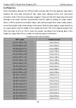
Page 71: ...ust be added on the output side of the VFD If the distance between the VFD and motor is 50 m to 100 m select the reactor according to the following table If the distance is longer than 100 m contact our technical support technicians Output reactor model selection VFD power Output reactor GD100 1R5G 2 PV OCL2 004 4 GD100 2R2G 2 PV OCL2 004 4 GD100 004G 2 PV OCL2 5R5 4 GD100 5R5G 2 PV OCL2 7R5 4 GD1...

Page 72: ...derate voltage of the output reactor is 1 15 Above options are external and the customer should specify the model when purchasing A 5 Filters C3 filters are built in GD100 PV series VFDs with rated power of equal to or greater than 4kW Jumper J10 determines the connection Connection method Open the lower cover find the location of J10 and insert the jumper terminals equipped with the VFD Note Afte...

Page 73: ...1R5G S2 PV 250 11 1 300 9 1 GD100 2R2G S2 PV 250 11 1 300 9 1 GD100 1R5G 2 PV 250 11 1 300 9 1 GD100 2R2G 2 PV 250 11 1 300 9 1 GD100 004G 2 PV 250 11 2 300 9 2 GD100 5R5G 2 PV 250 11 3 300 9 3 GD100 7R5G 2 PV 250 11 4 300 9 4 GD100 0R7G 4 PV 250 18 1 300 15 1 GD100 1R5G 4 PV 250 18 1 300 15 1 GD100 2R2G 4 PV 250 18 1 300 15 1 GD100 004G 4 PV 250 20 1 300 16 1 GD100 5R5G 4 PV 250 18 2 300 15 2 GD1...

Page 74: ... 2 Recommended configuration for VFDs with the boost module PP100 3R2 PV Solar pumping VFD Max DC input current Open circuit voltage degree of solar module 37 1V 45 1V A Module power 5Wp Modules per string strings Module power 5Wp Modules per string strings GD100 0R4G SS2 PV 12 250 4 1 300 3 1 GD100 0R7G SS2 PV 12 250 5 1 300 4 1 GD100 1R5G SS2 PV 12 250 8 1 300 7 1 GD100 0R4G S2 PV 12 250 4 1 300...

Page 75: ...tion Device Fuse FU M R S T R GD100 PV VFD B C A Diode D PV PV PV S COM HDI COM PV Input DC breaker QF2 VoltageDetectionCircuit RO1B RO1C 220V KM1 QH100 PV Switching Module A1 A2 PE Figure C 1 VFD power frequency PV switching solution See C 1 1 for specifications and model selection of QH100 PV switching module whose necessary low voltage apparatuses include QF1 KM1 QF2 FU and SPD C 1 2 details th...

Page 76: ... input Connects to the voltage detection board input and diode module positive pole PV PV input Connects to the voltage detection board input Switching module output Connects to the diode module negative pole S COM Voltage detection signal Switching on off signal corresponding to PV voltage higher lower than the threshold Connects to VFD terminals HDI and COM C 1 1 3 Installation dimensions 115 7 ...

Page 77: ...5 GD100 0R7G SS2 PV AS 16 16 GD100 2R2G S2 PV AS 40 40 GD100 1R5G SS2 PV AS 25 25 GD100 2R2G SS2 PV AS 40 40 GD100 0R7G 4 PV AS 10 12 GD100 1R5G 4 PV AS 10 12 GD100 2R2G 4 PV AS 10 12 GD100 004G 4 PV AS 25 25 55A 1600V GD100 5R5G 4 PV AS 25 25A 1000VDC 25 GD100 2R2G 2 PV AS 25 25 GD100 004G 2 PV AS 25 25 GD100 7R5G 4 PV AS 40 40 GD100 5R5G 2 PV AS 40 63A 1000VDC 40 GD100 011G 4 PV AS 50 50 GD100 7...

Page 78: ...AS 200 160A 1000VDC 170 160A 1600V GD100 055G 4 PV AS 200 250A 1000VDC 170 250A 1600V GD100 075G 4 PV AS 250 205 GD100 090G 4 PV AS 315 350A 1000VDC 245 350A 1600V GD100 110G 4 PV AS 350 265 GD100 132G 4 PV AS 350 400A 1000VDC 330 400A 1600V GD100 160G 4 PV AS 400 550A 1000VDC 400 550A 1600V GD100 185G 4 PV AS 500 500 GD100 200G 4 PV AS 500 600A 1000VDC 500 600A 1600V ...

Page 79: ... type does not implement auto switching The figure below shows the VFD dimensions Solar Pumping VFD Figure C 2 IP54 VFD dimensional drawing IP54 VFD dimensions unit mm Power kW Model W H D A B 37 GD100 037G 45 PV AS 650 1000 250 400 975 30 GD100 030G 45 PV AS 22 GD100 022G 45 PV AS 18 5 GD100 018G 45 PV AS 15 GD100 015G 45 PV AS 550 900 225 400 875 11 GD100 011G 45 PV AS 7 5 GD100 7R5G 45 PV AS GD...

Page 80: ...R7G SS25 PV AS 0 4 GD100 0R4G S25 PV AS GD100 0R4G SS25 PV AS Note The VFDs that do not implement auto switching do not have the suffix AS The VFDs 2 2kW are equipped with the boost module supporting auto switching For S25 and SS25 models with the boost module the DC input voltage cannot be greater than 440V For 45 models with the boost module the DC input voltage cannot be greater than 600V C 3 W...

Page 81: ...to terminal N L N AC input 1PH 220V AC input terminals connected to the grid PV input Solar cell panel input terminals U V W VFD output 3PH 1PH AC output terminals connected to pump motor Note 1PH motors must connect to terminals U and W Safety grounding Safety grounding terminal Each VFD must be grounded properly Note It is at the bottom of the chassis C 4 Parameter setting method Connect the ext...

Page 82: ... Keypad structure Installation hole Note The external keypad is optional for the VFDs 380V 2 2kW and the standard keypad of VFDs 380V 4kW can be used as the external keypad If the keypad is externally installed on an optional bracket it can be 20 meters away from the VFD at most Installation bracket Installation dimension ...

Page 83: ...3 5 120 3 5 GD100 0R4G SS2 PV 80 0 60 0 160 0 150 0 123 5 120 3 5 GD100 1R5G S2 PV 80 0 60 0 185 0 175 0 140 5 137 3 5 GD100 2R2G S2 PV 80 0 60 0 185 0 175 0 140 5 137 3 5 GD100 0R7G SS2 PV 80 0 60 0 185 0 175 0 140 5 137 3 5 GD100 1R5G SS2 PV 80 0 60 0 185 0 175 0 140 5 137 3 5 GD100 2R2G SS2 PV 80 0 60 0 185 0 175 0 140 5 137 3 5 GD100 0R7G 4 PV 80 0 60 0 185 0 175 0 140 5 137 3 5 GD100 1R5G 4 P...

Page 84: ...100 0R4G SS2 PV 80 0 160 0 35 4 36 6 123 5 120 3 5 GD100 1R5G S2 PV 80 0 185 0 35 4 36 6 140 5 137 3 5 GD100 2R2G S2 PV 80 0 185 0 35 4 36 6 140 5 137 3 5 GD100 0R7G SS2 PV 80 0 185 0 35 4 36 6 140 5 137 3 5 GD100 1R5G SS2 PV 80 0 185 0 35 4 36 6 140 5 137 3 5 GD100 2R2G SS2 PV 80 0 185 0 35 4 36 6 140 5 137 3 5 GD100 0R7G 4 PV 80 0 185 0 35 4 36 6 140 5 137 3 5 GD100 1R5G 4 PV 80 0 185 0 35 4 36 ...

Page 85: ... 4 PV 170 0 151 0 320 0 303 5 196 3 113 0 6 GD100 011G 4 PV 170 0 151 0 320 0 303 5 196 3 113 0 6 GD100 015G 4 PV 170 0 151 0 320 0 303 5 196 3 113 0 6 GD100 004G 2 PV 170 0 151 0 320 0 303 5 196 3 113 0 6 GD100 5R5G 2 PV 170 0 151 0 320 0 303 5 196 3 113 0 6 GD100 7R5G 2 PV 170 0 151 0 320 0 303 5 196 3 113 0 6 GD100 018G 4 PV 200 0 185 0 340 6 328 6 184 3 104 5 6 GD100 022G 4 PV 200 0 185 0 340 ...

Page 86: ...on Dimensions in flange installation unit mm Model W1 W2 W3 W4 H1 H2 H3 H4 D1 D2 Installation hole Nut specs GD100 004G 4 PV 170 2 131 150 9 5 292 276 260 6 167 84 5 6 M5 GD100 5R5G 4 PV170 2 131 150 9 5 292 276 260 6 167 84 5 6 M5 GD100 7R5G 4 PV191 2 151 174 11 5 370 351 324 12 196 3 113 6 M5 GD100 011G 4 PV 191 2 151 174 11 5 370 351 324 12 196 3 113 6 M5 GD100 015G 4 PV 191 2 151 174 11 5 370 ...

Page 87: ...GD100 045G 4 PV 352 332 306 13 580 400 570 80 238 133 8 9 M8 GD100 055G 4 PV 352 332 306 13 580 400 570 80 238 133 8 9 M8 GD100 075G 4 PV 352 332 306 13 580 400 570 80 238 133 8 9 M8 GD100 090G 4 PV 418 5 361 389 514 2 600 559 370 108 5329 5149 5 9 5 M8 GD100 110G 4 PV 418 5 361 389 514 2 600 559 370 108 5329 5149 5 9 5 M8 GD100 132G 4 PV 500 360 480 60 870 850 796 37 358 178 5 11 M10 GD100 160G 4...

Page 88: ...umping VFD Further information 86 Appendix E Further information E 1 Product and service inquiries Address any inquiries about the product to your local offices quoting the type designation and serial number of the unit in question ...

Page 89: ...201905 V1 1 6 6 0 0 1 0 0 4 3 0 201908 V1 1 6 6 0 0 1 0 0 4 4 5 ...

Reviews: