Goodrive600 series high-performance multifunction VFD
Function parameter list
-250-
Function
code
Name
Description
Default Modify
Note: After the selected operation is
performed, the function code is automatically
restored to 0. Restoring the default values
may delete the user password. Exercise
caution when using this function.
P01 group
––Start and stop control
Function
code
Name
Description
Default Modify
P01.00
Start mode
0: Direct start
1: Start after DC braking
2: Speed tracking restart 1
3: Speed tracking restart 2
0
◎
P01.01
Starting frequency of
direct start
Used to indicate the initial frequency during
inverter unit start. See P01.02 (Starting
frequency hold time) for detailed information.
Setting range: 0.00
–50.00Hz
0.50Hz
◎
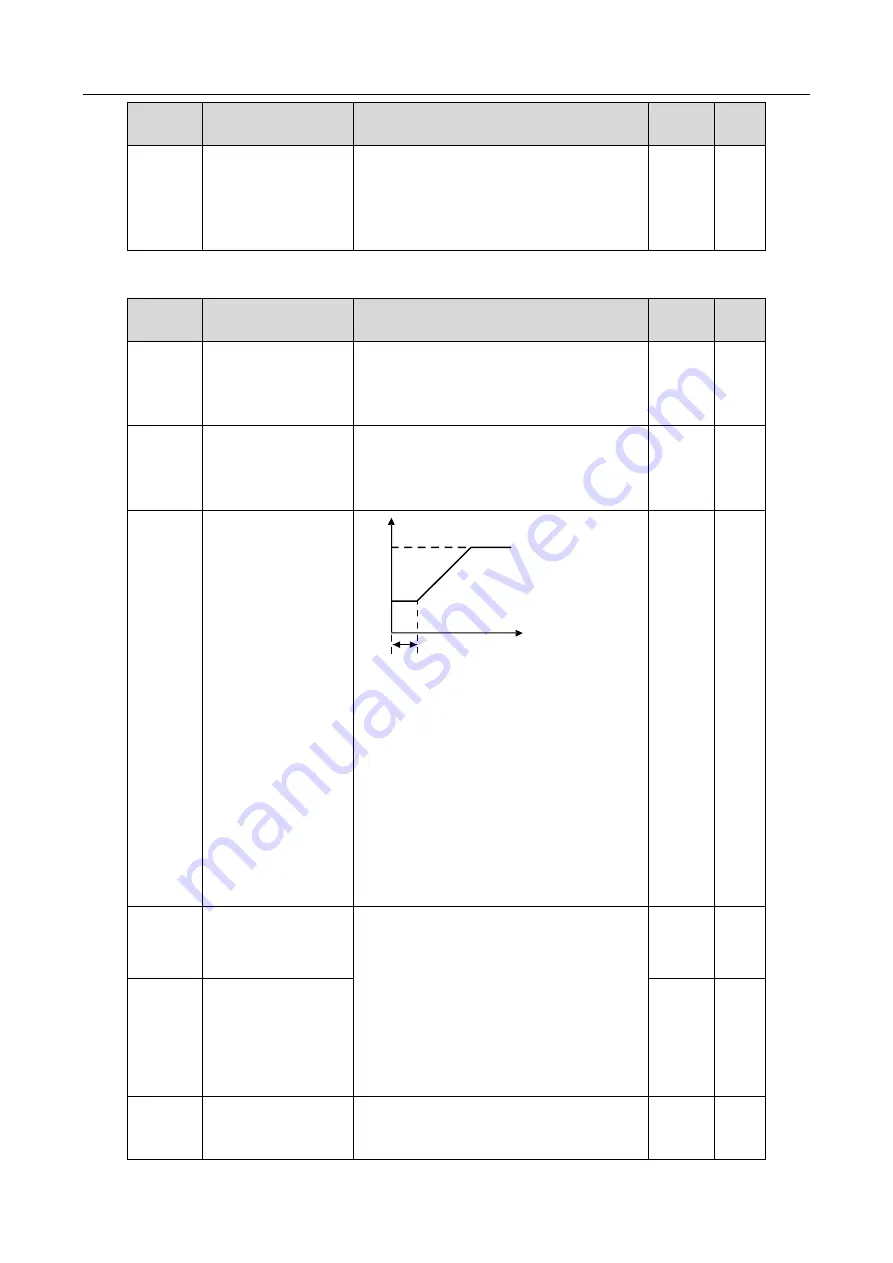
P01.02
Starting frequency hold
time
Output frequency f
fmax
t1
Time t
f1 set by P01.01
f1
t1 set by P01.02
Setting a proper starting frequency can increase
the torque during VFD start. During the hold time
of the starting frequency, the output frequency of
the inverter unit is the starting frequency. And
then, the inverter unit runs from the starting
frequency to the set frequency. If the set
frequency is lower than the starting frequency,
the inverter unit stops running and keeps in the
standby state. The starting frequency is not
limited in the lower limit frequency.
Setting range: 0.0
–50.0s
0.0s
◎
P01.03
Braking current before
start
The inverter unit performs DC braking with the
braking current before start and it speeds up
after the DC braking time. If the set DC braking
time is 0, DC braking is invalid.
Stronger braking current indicates larger braking
power. The DC braking current before start is a
percentage of the inverter unit rated current.
P01.03 setting range: 0.0
–100.0%
P01.04 setting range: 0.00
–50.00s
0.0%
◎
P01.04
Braking time before start
0.00s
◎
P01.05
ACC and DEC mode
Used to indicate the changing mode of the
frequency during start and running.
0: Linear type. The output frequency increases
0
◎


