EN - 5
5. CONTROLS
5.1 MANUAL START HANDGRIP
(Fig.8.A)
5.2
PUSH-BUTTON ELECTRIC START COM-
MAND
(Fig.8.B)
5.3 ENGINE BRAKE LEVER / CUTTING MEANS
(Fig.9.A)
5.4 DRIVE ON LEVER
(
Fig.9.B)
IMPORTANT
The engine must be started only with
the drive OFF.
IMPORTANT
Avoid moving the machine backwards
when the drive is ON.
5.5
CUTTING HEIGHT ADJUSTMENT
Do this when the cutting means is stationary.
• Adjustment
(See Fig.10.A)
6. USING THE MACHINE
IMPORTANT
For instructions on the engine and the bat-
tery (if equipped), refer to the corresponding manuals.
6.1 PRELIMINARY PROCEDURES
Place the machine in a stable horizontal position on the
ground.
6.1.1 Filling with oil and fuel
IMPORTANT
The machine is supplied without engine oil
and without fuel.
Before using the machine, refuel and top/up with oil; refer to
the owner's manual of the engine at par. 7.2.1/7.2.2.
6.1.2 Preparing the machine before starting work
NOTE
This machine can be used to mow lawns in vari-
ous ways;
a.
Preparation for grass cutting and collection in
the grass catcher:
1.
For side discharge models: make sure that the
guard (Fig. 11.A) is lowered and locked by the
safety lever (Fig. 11.B).
2.
Insert the grass catcher (Fig.11.C).
b.
Preparation for grass cutting and rear grass
discharge on the ground:
1.
Liftthereardischargeguard(Fig.12.A)andfitthepin
(Fig.12.B).
2.
For models with side discharge: make sure that the
guard (Fig. 12.C) is lowered and locked by the safety
lever (Fig. 12.D).
To remove the pin: see Fig.12.A/B.
c.
Preparation for grass mowing and chopping
(mulching function):
Lift the rear discharge guard (Fig.13.A) and insert the
chute plug (Fig.13.B) in the discharge opening.For models
with side discharge: make sure that the side discharge
guard (Fig. 13.C/D) is lowered and locked by the safety
lever (Fig. 13.D).
To remove the chute plug: see Fig.13.E.
d.
Preparation for grass cutting and side
discharge on the ground:
1.
Lift the rear discharge guard (Fig.14.A) and insert the
chute plug (Fig.14.B) in the discharge opening.
2.
Slightly push the safety lever (Fig.14.C) and lift the
side discharge guard (Fig.14.D).
3.
Insert the side discharge chute (Fig.14.E).
4.
Close the side discharge guard (Fig.14.D) so as to
lock the side discharge chute (Fig.14.E).
To remove the side discharge chute:
5.
Slightly push the safety lever (Fig.14.C) and lift the
side discharge guard (Fig.14.D).
6.
Release the side discharge chute (Fig.14.E).
6.1.3 Handle inclination adjustment
(
Fig.15/16)
Do this when the cutting means is stationary.
6.2 SAFETY CHECKS
Always carry out the safety checks before use.
6.2.1 Safety check before every use
• Check the integrity and the correct mounting
of all components of the machine;
• make sure that all fastening devices are correctly tightened;
• keep all surfaces of the machine clean and dry.
6.2.2 Machine operating test
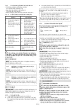
Action
Result
1.
Start the machine
(par. 6.3).
2.
Release the engine
brake lever / cutting
means.
1.
The cutting means
should move.
2.
The levers should
return automatically
and rapidly to the
neutral position, the
motormustswitchoff
and the cutting means
must stop within a few
seconds.
Summary of Contents for CP1 434 K
Page 5: ...A C F B H I J D G E 2 1 kW min s n 9 5 8 1 kg 2 3 6 4 7 Type Art N ...
Page 6: ...B A C 3 mm 0 mm 4 3 ...
Page 7: ...1 2 3 5 6 1 2 3 4 ...
Page 8: ...A B 9 A B 8 1 2 3 4 7 ...
Page 9: ...10 A A B C 11 A D B C 12 ...
Page 10: ...D C A B E 13 B C D D A E E 14 ...
Page 11: ...15 I ...
Page 12: ...B 3 mm II 16 0 mm ...
Page 13: ...17 A B 18 B D A A 19 20 2 1 ...
Page 14: ...21 A D B C A 22 ...
Page 15: ...25 23 A B D C A B C ...
Page 16: ...27 28 26 A B A 24 ...
Page 85: ...171506302 0 12 2018 ...

