background image

15

TROUBLESHOOTING/MAINTENANCE

M

A

I

N

T

E

N
A
N
C

E

MAINTENANCE

MAINTENANCE SAFETY
PRECAUTIONS

WARNING

After ANY adjustments, repair or service and
BEFORE use, make sure all attaching hardware
is tightened securely - otherwise injury or dam-
age may result.

CAUTION

DO NOT over tighten hardware attaching to
the frame. This could cause damage to the
frame tubing.

SUGGESTED MAINTENANCE
PROCEDURES

1. Before using your wheelchair, make sure all nuts

and bolts are tight. Check all parts for damage or
wear and replace. Check all parts for proper ad-
justment.

2. Keep quick-release axles free of dirt and lint to

ensure positive locking and proper operation. Re-
fer to ADJUSTING THE QUICK-RELEASE AXLE
in PROCEDURE 4 of this manual.

3. If equipped, oil quick-release axles at least once (1)

a month (3-in-1

®


 oil


or equivalent).

3-in-1 oil - Registered trademark of American Home
Products Corporation.

T

R

O

U
B

L

E
S
H

O
O

T

I

N

G

TROUBLESHOOTING

4. The wheels and tires should be checked periodi-

cally for cracks and wear, and should be replaced
when necessary by your authorized dealer or by a
qualified technician.

5. Periodically check handrims to ensure they are

securely attached to the rear wheels. Refer to
REPLACING REAR WHEEL HANDRIM in PRO-
CEDURE 4
 of this manual.

6. Periodically adjust wheel locks in correlation to tire

wear. Refer to WHEEL LOCK ADJUSTMENT in
PROCEDURE 6 of this manual.

7. Periodically check front caster and rear wheel hubs

to make sure they are clean. Use a Teflon

®

 lubri-

cant if necessary.

8. Check Upholstery for sagging, rips or tears.

Teflon - Registered trademark of E.I. Du Pont Nemours
and Company.

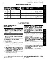
CHAIR

CHAIR

SLUGGISH

CASTERS

SQUEAKS

LOOSENESS

CHAIR

SOLUTIONS

VEERS

VEERS

TURN OR

FLUTTERS

AND

IN CHAIR

WHEELS

RIGHT

LEFT

PERFORMANCE

RATTLES

X

X

X

X

X

If pneumatic, check tires
for correct and equal
pressure.

X

X

X

X

Check for loose stem
nuts and bolts.

X

X

X

Check that both casters
contact the ground at
the same time.

WARNING

DO NOT use the wheelchair unless it has the
proper tire pressure (p.s.i.). DO NOT overinflate
the tires. Failure to follow these suggestions may
cause the tire to explode and cause bodily harm.
Recommended tire pressure is listed on the side
wall of the tire.

Summary of Contents for Tracer DLX

Page 1: ...d Maintenance Manual Tracer SX Tracer SX Recliner Tracer Titan Tracer DLX DEALER THIS MANUAL MUST BE GIVENTOTHE USER OF THEWHEELCHAIR USER BEFORE USINGTHISWHEELCHAIR READTHIS MANUALAND SAVE FOR FUTURE...

Page 2: ...ENT WITHOUT FIRST READING AND UNDERSTANDING THIS MANUAL IF YOU ARE UNABLE TO UNDERSTAND THE WARNINGS CAUTIONS AND INSTRUCTIONS CONTACT A HEALTHCARE PROFESSIONAL DEALER OR TECHNICAL PERSONNEL IF APPLIC...

Page 3: ...21 ADJUSTING SEAT DEPTH 21 ADJUSTING SEAT WIDTH 21 PROCEDURE 4 REAR WHEELS 23 REMOVING INSTALLING THE REAR WHEELS 23 ADJUSTING THE QUICK RELEASE AXLE 24 REPLACING REAR WHEEL HANDRIM 24 REPLACING REPA...

Page 4: ...ends that wheelchair users NOT be transported in vehicles of any kind while in wheelchairs As of this date the Department of Transportation has not approved any tie down systems for transportation of...

Page 5: ...oads streets or highways DO NOT climb go up or down ramps or traverse slopes greater than 9 DO NOT attempt to move up or down an incline with a water ice or oil film DO NOT attempt to ride over curbs...

Page 6: ...th will be required for approximately the last twenty 20 degrees of incline reverse recline Make sure to use proper body mechanics use your legs or seek assistance if necessary to avoid injury Assista...

Page 7: ...n forward out of the wheelchair any further thanthelengthofthearmrests Makesurethecastersare pointingintheforwardpositionwheneveryouleanforward This can be achieved by advancing the wheelchair and the...

Page 8: ...sition the front casters so that they are extended as far forward as possible and engage wheel locks DO NOTATTEMPTTOREACHOBJECTSIFYOUHAVE TO MOVE FORWARD IN THE SEAT OR PICK THEM UP FROM THE FLOOR BY...

Page 9: ...elchair frame when lifting the wheelchair and stabilizing the wheelchair when the wheelchair is being lowered to the ground The first assistant should stand on the sidewalk and turn the wheelchair so...

Page 10: ...mmends orderingtheSeatPositioningStrapasanadditional safeguard for the wheelchair user Do not attempt to lift a wheelchair by lifting on any removable detachable parts Lifting by means of any removabl...

Page 11: ...r is equipped with carry straps the wheelchair may be closed by pulling up on the straps Detent Pin Recliner Models FOLDING 1 Push in detent pin on one side of spreader bar 2 While holding spreader ba...

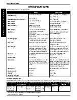
Page 12: ...lchair is equipped With 24 inch Rear Wheels Overall Width Shipping Weight approx Weight approx Rear Axle Back Height Seat to Floor Overall Depth w o riggings 34 inches 61 lbs 51 lbs Permanent 23 inche...

Page 13: ...posite Urethane Pneumatic or Pneu matic Flat Free Insert 24 inch Composite Urethane Standard Composite Standard andChrome Plated Steel High Mount 6 x 1 inch Urethane 8 x 1 inch Solid Rubber Standard a...

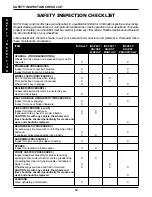
Page 14: ...of wear and looseness X X Wheel locks easy to engage X X RECLINER PROCEDURE 8 Inspect reclining mechanisms to ensure they are clean and work freely X X SEAT AND BACK UPHOLSTERY PROCEDURE 3 Inspect fo...

Page 15: ...r cracks and wear and should be replaced when necessary by your authorized dealer or by a qualified technician 5 Periodically check handrims to ensure they are securely attached to the rear wheels Ref...

Page 16: ...ootplate is perpendicular to wheelchair 2 Place the hinge plates on the swingaway footrest onto the hinge pins on the wheelchair frame 3 Push the swingaway footrest towards the inside of the wheelchai...

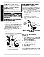
Page 17: ...of the wheelchair Phillips Screw Spacer Locknut Bolt and Locknut Heel Loop FIGURE 3 HEEL LOOP REPLACEMENT 1 Placelegrestassemblyontheoutsideofthewheel chair and install the hinge plates onto the hinge...

Page 18: ...into the DOWN VERTICAL position when the desired armrest height is achieved WARNING AfterANYadjustments repairorserviceandBEFORE use make sure all attaching hardware is tightened securely otherwisein...

Page 19: ...FOREusing FIGURE 3 USING OR REPLACING FLIP BACK ARMREST Arm Socket Armrest Release Button Front or Back of the Armrest Front Tube Armrest Front Tube Washer Spacer Armrest Rear Tube Nut Armrest Mountin...

Page 20: ...kcanes 2 Remove the screw coved washers and locknut that secure one 1 back cane to the wheelchair frame NOTE It is necessary to remove only one 1 back cane to replace the back upholstery 3 Pull the lo...

Page 21: ...G SEAT WIDTH FIGURE 6 WARNING Adjusting the seat width of the wheelchair MUST be performed by a qualified technician 1 Remove the existing back and seat upholstery from the wheelchair Refer to REPLACI...

Page 22: ...des will stay attached to rear canes b Remove upholstery screws c Remove crossbraces from seat guides 3 Remove the hardware that secures the two 2 existing crossbraces together FIGURE 6 4 Perform one...

Page 23: ...1 REMOVING INSTALLING THE REAR WHEELS PERMANENT AXLES Locknut Dust Cap Axle Mounting Hole Rear Wheel Hex Screw Spacer PERMANENT AXLE WARNING Make sure the detent pin and locking pins of the quick rel...

Page 24: ...rom the wheelchair Refer to REMOVING INSTALL ING THE REAR WHEELS in this section of the manual 2 Depress detent pin in the quick release axle and slide axle through the wheel hub 3 Release detent pin...

Page 25: ...e positioned in the same mounting hole BEFORE using the wheelchair otherwise injury can occur 4 Repeat STEPS 1 3 for the opposite front caster FIGURE 2 FRONT CASTER MOUNTING ADJUSTMENTS Used with 6 in...

Page 26: ...engaged in adjustment holes and ensure both anti tippers are adjusted to the same height 4 Check to make sure that a 1 1 2 to 2 inch clearance between the bottom of the anti tipper wheels and the gro...

Page 27: ...and locknut 5 Engage wheel lock and push against the wheel chair and determine if wheel lock engages the wheel lock shoe enough to hold the wheelchair 6 Repeat the above procedures until the wheel lo...

Page 28: ...FLOOR HEIGHT FIGURE 1 CHANGING SEAT TO FLOOR HEIGHT ADULT HEMI FRAME STYLE WARNING When changing the seat to floor height the heightoftheanti tippersmustbeadjustedaswell NOTE Invacare recommends that...

Page 29: ...AME STYLE X X FORWARD MOUNTING POSITIONS DO NOT USE WARNING TRACER SX RECLINER ONLY Mount the rear wheels in the Rear Wheel Offset Bracket ONLY NEVER reposition the rear wheels to the forward position...

Page 30: ...MUST BE attached at all times Anti tippers MUST be fully engaged Ensure that the release button of the anti tipper fully pro trudes out of the hole on the bottom of the wheelchair frame Ensure both a...

Page 31: ...ry FIGURE 3 1 Remove the headrest pillow Refer to REPLAC ING THE HEADREST PILLOW in this procedure of the manual 2 Remove the six 6 mounting screws that se cure the headrest upholstery to the headrest...

Page 32: ...ing Screws FIGURE 3 REPLACING THE HEADREST BACK UPHOLSTERY Back Cane Headrest Upholstery Headrest Extension Tube NOTE Toremoveandinstallthebottomtwo 2 mount ing screws of the back upholstery the wheel...

Page 33: ...d locknut Securely tighten R E C L I N E R Axle Mounting Screw Rear Wheel Spacer Rear Wheel Offset Bracket Locknut FIGURE 5 REMOVING INSTALLING THE REAR WHEELS Rearward Mounting Positions Rear Wheel O...

Page 34: ...tch and Cane Carrier INSTALLING THE AMPUTEE BRACKET FIGURE 1 1 Refer to the following chart or FIGURE 1 to deter minethemountingpositionoftheamputeebracket 2 Install the amputee bracket on the wheelch...

Page 35: ...Align the strap with the back upholstery screw mounting hole 6 Reinstall the back upholstery screw and washer and secure the strap to the wheelchair FIGURE 2 INSTALLING THE SEAT POSITIONING STRAP Sea...

Page 36: ...sed your Invacare product In the event you do not receive satisfactory warranty service please write directly to Invacare at the address at the bottom of this page Provide dealer s name address the pr...

Reviews: