User Guide 003
3
UG003.0
September 17, 2014
Submit Document Feedback
Resistor Settings” table and the design guide matrix in the
ISL8272M
datasheet for recommended values.
PMBus Option
ISL8272MEVAL1Z can be evaluated for all features using the
provided ZLUSBEVAL3Z dongle and PowerNavigator™ evaluation
software. Follow these steps to evaluate ISL8272M with PMBus
option.
1. Install PowerNavigator™ software from the following Intersil
website:
www.intersil.com/powernavigator
2. Set ENABLE switch to “DISABLE”.
3. Connect Load to VOUT lug connectors (J7-J8 and J9-J10).
4. Connect power supply to VIN connectors (J5 and J6). Make
sure power supply is not enabled when making connection.
5. Turn power supply on.
6. Connect ZLUSBEVAL3Z dongle (USB to PMBus™ adapter) to
ISL8272MEVAL1Z board to the 6-pin male connector labeled
as “PMBus DONGLE IN”.
7. Connect supplied USB cable from computer USB to
ZLUSBEVAL3Z dongle.
8. Launch PowerNavigator™ software.
9. It is optional to load a predefined set-up from a configuration
file using the PowerNavigator™ software. The ISL8272M
device on the board operates in pin-strap mode from factory
default, but the user may modify the operating parameters
through the evaluation software or by loading a predefined
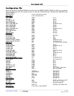
set-up from a configuration file. A sample
“Configuration File”
on page 6
is provided and can be copied to a notepad editor
to make desired changes. The default pin-strap
configurations will be overwritten if a user-defined
configuration file is loaded.
10. Set ENABLE switch to “ENABLE”. Alternatively, the PMBus
ON_OFF_CONFIG and OPERATION commands may be used
from the PowerNavigator™ software to allow PMBus Enable.
11. Monitor and configure the ISL8272MEVAL1Z board using the
PMBus commands in the evaluation software. To store the
configuration changes, disable the module and use the
command STORE_USER_ALL. To restore factory default
settings, disable the module and use the command
RESTORE_FACTORY and STORE_USER_ALL.
12. PowerNavigator™ tutorial videos are available at Intersil
website.
www.intersil.com/powernavigator
13. For sequencing via Digital-DC Bus (DDC) or to evaluate
multiple Intersil digital power products using a single
ZLUSBEVAL3Z dongle, ISL8272M can be daisy chained with
other digital power evaluation boards. PMBus address can be
changed by placing a 1% standard 0603 resistor at the R4
placeholder location on the bottom layer. Refer to the “SMBus
Address Resistor Selection” table in the
ISL8272M
datasheet
for recommended values.
Thermal Considerations and
Current Derating
Board layout is very critical in order to make the module operate
safely and deliver maximum allowable power. To work in the high
temperature environments and carry large currents, the board
layout needs to be carefully designed to maximize thermal
performance. To achieve this, select enough trace width, copper
weight and the proper connectors.
The ISL8272MEVAL1Z evaluation board is designed for running
50A at room temperature without additional cooling systems
needed. However, if the output voltage is increased or the board
is operated at elevated temperatures, then the available current
is derated. Refer to the derated current curves in the
ISL8272M
datasheet to determine the maximum output current the
evaluation board can supply.
JA
is measured by inserting a
thermocouple inside the module to measure peak junction
temperature.


