Intersil ISL76683 User Manual Download Page 6

Application Note 1657

6

Intersil Corporation reserves the right to make changes in circuit design, software and/or specifications at any time without notice. Accordingly, the reader is 

cautioned to verify that the Application Note or Technical Brief is current before proceeding.

For information regarding Intersil Corporation and its products, see www.intersil.com

AN1657.0

August 12, 2011

Data Collection

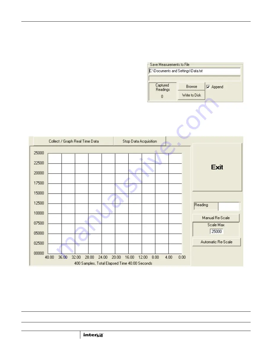
In the ISL76683 Light Sensor Evaluation Software window, use 
the Collect/Graph Real Time Data dialog (Figure 13) to acquire 
and graph measurements.
• Click Collect/Graph Real Time Data to sample data. Samples 

are taken and plotted, and values are displayed in the Reading 
field on the right side of the dialog. The Reading field displays 
the value of the ADC output coming out of the sensor in 
accordance with the mode that is engaged.

• Click Stop Data Acquisition to stop data sampling.

• Click Exit to close the entire program.

• In  the  Scale Max text box, enter a maximum value for the scale 

(vertical axis), and click Manual Re-Scale to re-set.

• Click Automatic Re-Scale to re-scale the vertical axis to an 

appropriate field of view. This feature is useful if the sampled 
data is out of the range of the graph or if you need to zoom in 
on the data.

Saving Measurements to File

Use the Save Measurements to File dialog box in the lower right 
corner of the ISL76683 Light Sensor Evaluation Software window 
to save a series of measurements to disk. Click Browse to enter a 
filename and select a file path. Click Write to Disk to write the 
current graph data to disk.

FIGURE 14. SAVE MEASUREMENTS TO FILE

FIGURE 13. GRAPHICAL REAL-TIME DATA COLLECTION

Summary of Contents for ISL76683

Page 1: ...s 98 NT 2000 XP USB Port Hardware Setup The PC and printed circuit board PCB should not be connected via the USB until after the evaluation software has been installed satisfactorily see Software Setup on page 2 To set up the hardware 1 Connect the USB 2 0 cable first to the PC and then to the evaluation board The USB cable is the only connector needed 2 If a dialog appears asking about installing...

Page 2: ...ntroller board ISLUSBCEVAL1Z REV A The firmware allows the evaluation software to communicate with the ISL76683 evaluation board through a PC operating on Windows 98 NT 2000 XP Installing the Software Download and run Intersil_ALS_ISL76683_Installer_V100 exe The dialog shown in Figure 2 appears Follow the instructions on each screen for installing the software The PC and PCB should not be connecte...

Page 3: ...76683 Intersil_ALS_ISL76683 2 Double click the program name The Intersil Light Sensor Demo window shown in Figure 3 appears 3 In the Device Select dropdown menu select ISL76683 4 The ISL76683 Light Sensor Evaluation Software window shown in Figure 4 opens This window is the main interface for demonstrating the capabilities of ISL76683 FIGURE 3 SOFTWARE STARTUP FIGURE 4 ISL76683 LIGHT SENSOR EVALUA...

Page 4: ... put the ISL76683 into power down mode MEASUREMENT MODE SELECTION The ISL76683 contains two photodiodes Diode 1 is sensitive to both visible and infrared light while Diode 2 is sensitive mostly to infrared light Measurement Mode 1 is Diode 1 only and Measurement Mode 2 is Diode 2 only Measurement Mode 3 is a sequential Mode 1 and Mode 2 with an internal subtract function Diode 1 Diode 2 You can se...

Page 5: ...n the ISL76683EVAL1Z evaluation board or you can set it to be polled automatically To poll it manually click Sample External Int Pin To poll it automatically click the Poll Interrupt check box to select it With interrupt limits set you can begin collecting data Data is collected within the upper and lower limits you selected In the Interrupt Control dialog in the Interrupt Monitor area black boxes...

Page 6: ...ding field displays the value of the ADC output coming out of the sensor in accordance with the mode that is engaged Click Stop Data Acquisition to stop data sampling Click Exit to close the entire program In the Scale Max text box enter a maximum value for the scale vertical axis and click Manual Re Scale to re set Click Automatic Re Scale to re scale the vertical axis to an appropriate field of ...

Reviews: