

3
AN1391.0
March 10, 2008
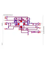
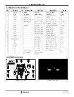
ISL6443AEVAL2Z Bill of Materials
ITEM
REFERENCE
QTY
PART NUMBER
PART TYPE
DESCRIPTION
VENDOR
1
P1 to P12
12
1514-2
Test Point
Turret 0.281 Height
Keystone
2
D1, D2
2
BAT54HT1G
Diode, Schottky
30V, 200mA
On Semi
3
C4
1
C1608X5R0J106
Cap, Ceramic, X5R
10µF, 6.3V, 0603, X5R
TDK
4
C30, C31
2
10TPB220M
Cap, POSCAP
220µF, 10V
Panasonic
5
C20, C21
2
C3225X5R1C106KT
Cap, Ceramic, 1210
10µF, 16V, 1210, X5R
TDK
6
L1, L2
2
DO3316P-682ML
SMT Power Inductor
6.8µH, ±20%, 4.6A, 27m
Ω
Coilcraft
7
C1
1
Capacitor, Ceramic,
0603 4.7
µF, 20%, 6.3V, 0603
Generic
8
Q1, Q2
2
FDS6912A
Dual NFET
6A, 30V, Dual NFET, SO8
Fairchild
9
C5, C7
2
Cap, Ceramic, 0603
0.1µF, 10%, 16V
Generic
C2, C3
2
Cap, Ceramic, 0603
0.01µF, 10%, 16V
Generic
10
C6
1
Cap, Ceramic, 0603
1.0µF, 10%, 16V
Generic
11
C32
1
Cap, Ceramic, 0805
10µF, 10%, 6.3V
Generic
12
C33, C34
2
NOT POPULATED
-
13
R8
1
Resistor, Film
100
Ω
, 0603, 1%, 1/16W
Generic
14
R1, R3, R6, R7, R9
5
Resistor, Film
1k
Ω
, 0603, 1%, 1/16W
Generic
15
R11
1
Resistor, Film
2k
Ω
, 0603, 1%, 1/16W
Generic
16
R2
1
Resistor, Film
324
Ω
, 0603, 1%, 1/16W
Generic
17
R5, R10
1
Resistor, Film
95.3k
Ω
, 0603, 1%, 1/16W
Generic
18
R12
1
Resistor, Film
5.11k
Ω
, 0603, 1%, 1/16W
Generic
19
R4
1
Resistor, Film
806
Ω
, 0603, 1%, 1/16W
Generic
20
Q3
1
IRLML6401PBF
Single NFET
Power MOSFET
IR
21
U1
1
ISL6443AIRZ
300kHz, Dual PWM
Controller
Intersil
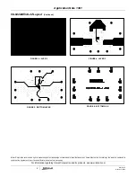
ISL6443AEVAL2Z Layout
FIGURE 1. TOP SILK
FIGURE 2. TOP LAYER
ISL6443AEVAL2Z
ISL6443AEVAL2Z
Application Note 1391


