


IS-1500 User Guide
Thales Visionix, Inc.
MNL- 0024 (D)
Page 11 of 59
U
NDERSTANDING
T
RACKING
This section is intended for those users who wish to better understand the tracking data produced by the IS-1500 and how it acquires
that information. It starts with the basics by briefly reviewing common terms and the Cartesian coordinate reference frame. From
there it moves on to discuss how the IS-1500 uses the InertiaCam’s NavChip IMU and camera to track its position and orientation.
In explaining how the tracking works, there are many general tips for usage that come up in this section. A brief bullet list of these tips
is provided in the Summary subsection.
This section uses many graphs and screenshots from the sfStudio program to illustrate the topics covered. For users who wish to follow
along and view live motion tracking data, it may be beneficial to first go through the IS-1500 Quick Start Guide or the Installation
section to set up the system before proceeding.
2.1
Tracking Basics
The tracking environment (or tracking area) broadly refers to the area the IS-1500 is being used in. The tracking data produced by
the IS-1500 uses a Cartesian (rectangular) coordinate reference frame to describe position and orientation within the tracking
environment.
The tracking data produced by the IS-1500 reflects the InertiaCam’s position and orientation, as defined by the tracker reference
frame, relative to the world reference frame. The X, Y, and Z position of the tracker is reported in meters. Orientation is described
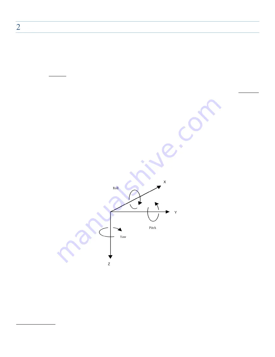
using Euler angles to indicate roll, pitch, and yaw.
As illustrated in Figure 3, roll, pitch, and yaw are the rotations around the X, Y, and Z axes of the world reference frame. As such, roll
changes the heading of the YZ plane of the tracker reference frame, pitch changes the XZ plane, and yaw changes the XY plane.
Figure 3 – Rotational Axes
An origin point and X, Y, and Z axes for the world reference frame are defined by the system when it is initialized. The origin point
defines the location in the tracking environment at which (X, Y, Z) is (0, 0, 0). When the IS-1500 is first initialized, the only sensory data
it can rely on to create a world reference frame is the direction of gravity. Therefore, it initializes using the accelerometers to determine
the direction of gravity. The Z axis is always in the direction of gravity, defining pitch and roll, while the direction of the X axis, defining
yaw, is effectively arbitrary. Using a right handed coordinate reference frame, the Y direction is 90° clockwise along the X axis. By
default, the IS-1500 sets the world origin point as the InertiaCam’s position when tracking is first initialized. As will be discussed in the
PRA Fiducial Tracking subsection, this initial world reference frame can be changed later by using a fiducial constellation to provide
the system with a global point of reference.