CompactGC manual
8
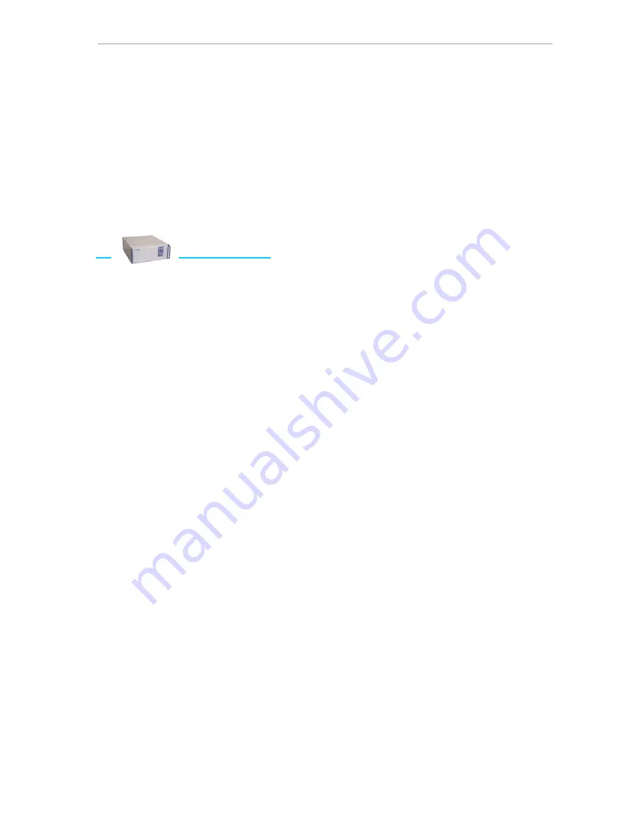
The front half of the instrument contains the ‘chromatography hardware’: on the right
side the valve oven for (maximum 3) heated valves, in the middle the isothermal
column oven(s) (maximum 3), on the left side the detector compartment, for up to 3
detectors. A module for cryogenic trapping, in case of trace gas analysis, can be
installed in place of one of the column ovens.
On the back half of the instrument, from right to left side, the power supply, the digital
gas supply, and detector controllers can be seen.
3.1
Digital
gas
supply
The gas control of the instrument is fully digital, and can be present in two types of
modules:
•
Carrier Gas Module (CGM) for carrier gas
•
Detector Gas Module (DGM) for detector gasses
CGM
The Carrier Gas Module is a sophisticated carrier gas supply device, which can be
operated in the following modes:
•
Constant pressure
•
Programmed pressure
•
Pressure pulse (pressure surge)
Four different gasses can be used: helium, hydrogen, nitrogen and argon. In case of
change of carrier gas type, recalibration of the splitflow is needed. Contact your
service organization for more information. Hydrogen is not recommended for safety
reasons.
Constant pressure
The most common used operating mode is constant pressure, with digital control of the
split flow. See figure 3.2.
In this diagram, the constant pressure is obtained by the upper proportional valve and
pressure sensor (P). The lower proportional valve and pressure sensor, in combination
with a temperature compensated restrictor are controlling the split flow.
Normally, the optimum flow for a certain type of column is the starting point of method
development. The needed pressure can be determined by measuring the flow on the
detector outlet, of can be calculated using the available flow calculator (CGC editor).


