


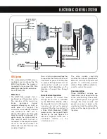


ACTUATOR
MANIFOLD
BYPASS
VALVE
CHARGER AIR
COOLER
MAINIFOLD
AIR
INLET
ORIFICE
AIR
FILTER
exhaust
out
air
BCS
45
International
®
VT 275 V6 Engine
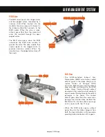
Turbocharger Actuator
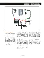
• The pneumatic actuator for the bypass
valve receives intake manifold boost
pressure from the intake elbow through a
plastic tube. When the Pulse Width
Modulated (PWM) signal to the boost
control solenoid is 100%, the valve is
open, and the boost pressure is vented to
the inlet duct. With boost vented, the
pneumatic actuator will be in the
relaxed position.
• When conditions occur that would result in
higher boost pressure than desired, the
ECM reduces the PWM signal to 0%. The
low signal causes the valve to close, boost
builds in the actuator, and if boost is high
enough, the actuator opens the diverter valve.
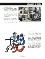
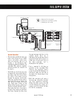
Actuator Line Routing
• The ECM controls the venting of the
actuator through the Boost Control
Solenoid (BCS). Proper operation of the
pneumatic actuator is dependent on the
routing of the pneumatic lines. The
actuator is connected through the black
plastic tube to the rubber tee at the intake
manifold elbow. The rubber tee at the
intake manifold elbow is also connected to
the BCS through a black plastic tube. The
BCS is then connected to atmospheric
pressure in the turbocharger inlet duct
with a green plastic tube. When the BCS
is open, the pressure in the black tube is
vented to atmosphere through the green
tube. When the BCS is closed, pressure in
the manifold will build in the actuator.
AIR MANAGEMENT SYSTEM
P
PN
NEEU
UM
MAATTIIC
C AAC
CTTU
UAATTO
OR
R
P
PN
NEEU
UM
MAATTIIC
C AAC
CTTU
UAATTO
OR
R
C
CO
OM
MP
PR
REES
SS
SO
OR
R IIN
NLLEETT
C
CO
OM
MP
PR
REES
SS
SO
OR
R IIN
NLLEETT


