


IRDC38063-P1V2
3/21/2017
6
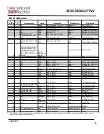
Bill of Materials
•The electrolytic input capacitor used on this demo board is to eliminate the impact of the parasitic inductance of a long input power cable. It may not
be necessarily needed in real applications.
Item
Number
Quantit
y
Part Reference
Value
Description
Manufacturer
Part Number
1
1 C1
330uF
SMD Electrolytic, F size, 25V, 20% Panasonic
EEE-FK1E331P
2
1 C8
2200pF
2200pF, 0603, 50V, NPO
TDK
C1608C0G1H222J
3
1 C79
100 pF
50V, 0603, NP0, 5%
Murata
GRM1885C1H101JA01D
4
1 C11
390 pF
50V, 0603, NP0, 5%
Murata
GRM1885C1H391JA01D
5
1 C26
22nF
0603,50V,X7R
Murata
GRM188R71H223KA01D
6
4 C29 C30 C31 C32
22uF
22uF,1206, 25V, X5R, 20%
TDK
C3216X5R1E226M160AB
7
6
C10 C36 C42 C53 C69
C78
0.1uF
0603, 50V, X7R, 10%
Panasonic
ECJ-1VB1H104K
8
1 C35
1uF
0603, X5R, 25V, 20%
TDK
C1608X5R1E105M
9
7
C43 C44 C45 C46 C47 C48
C49
47uF
0805, 6.3V, X5R, 20%
TDK
C2012X5R0J476M125AC
10
18
EXTLOADCTRL EN/FCCM
I-MONITOR IMON PGND
PGOOD SW SYNC TMON
VCC+ VCC- VDDQ VIN
VIN_+ VOUT_+ VOUT_- VP
VSENSE
0.075"
SQ_SMT_Te
stPoint
Keystone Electronics 5000 and 5006
11
1 J1 (CLK, Data,GND, Alert)
Header-4P
4x1
12
1 Bode1
Header-2P
2x1
13
1 C41
2.2uF
0603, 10V, X5R
TDK
C1608X5R1A225M080AC
14
1 C68
10uF
0805, 10V, X5R
TDK
C2012X5R1A106M125AB
15
1 C80
10uF
0603, 10V, X5R, 20%
Murata
GRM188R61A106ME69D
16
1 R19
7.5k
0603,1/10W,1%
Rohm
MCR03EZPFX7501
17
1 L1
215nH
0.215uH, DCR=0.29mohm
Cyntec
PCDC1008-R215EMO
18
1 M1
IRF6721
Direct Fet 30V SQ
International Rectifier IRF6721STRPbF
19
1 R1
1.21k
0603,1/10W,1%
Rohm
MCR03EZPFX1211
20
1 R2
5.62k
0603,1/10W,1%
Rohm
MCR03EZPFX5621
21
1 R9
66.5k
0603,1/10W,1%
Rohm
MCR03EZPFX6652
22
1 R4
182
0603,1/10W,1%
Rohm
MCR03EZPFX1820
23
1 R6
20
0603,1/10W,1%
Rohm
CRCW060320R0FKEA
24
11
R8 R10 R11 R14 R25 R35
R36 R37 R39 R40 R41
0 ohm
0603,1/10W
Rohm
CRCW06030000Z0EA
25
1 R18
49.9k
0603,1/10W,1%
Rohm
MCR03EZPFX4992
26
4 R22 R26 R51 R52
0 ohm
1206,1/4 W
Panasonic
ERJ-8GEY0R00V
27
4 R42 R43 R44 R46
0.2 ohm
0805,1/8W, 5%
CTS
73L3R20J
28
1 R47
1.5k
0603,1/10W,1%
Rohm
MCR03EZPFX1501
29
2 R48 R49
10k
0603,1/10W,1%
Rohm
MCR03EZPFX1002
30
1 R50
20 mohm
1206,1/2W,1%
Ohmite
LVK12R020FER
31
2 R23 R31
4.99k
0603,1/10W,1%
Rohm
MCR03EZPFX4991
32
1 U2
MIC4452/SO
8
Mosfet driver Non-inverting SO-8
Micrel
MIC4452YM
33
1 U1
IR38063
IR38063 5mm X 7mm
International Rectifier IR38063
34
2 Pvin+, Vout+ Connector
Red
Screw Terminal 30A
Keystone Electronics
8199-2
35
2 Pvin-, Vout- Connector
Black
Screw Terminal 30A
Keystone Electronics
8199-3